SpectraPure
®
Inc
. Fax 480.894.6109 Fax us toll-free 1.877.527.7873
sales@spectrapure.com www.spectrapure.com
7
SpectraPure
®
You can cut the tubes in two and extend them with 1/4" OD x 1/8" ID vinyl
tubing to an additional distance of fifteen feet.
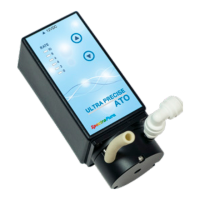
There are 6 lights, arranged vertically along the left side of the ATO. They
are numbered 0, 2, 4, 6, 8 and 10. They are used in different modes to
display various values and settings.
There are two buttons, UP ( ) and DOWN ( ). They are used to modify
the runtime characteristics of the pump. Repeated presses of the UP button
steps the indicator lights up to light 10. One more press of the UP button
returns to light 0. Likewise, with the light 0 blinking, one press of the
DOWN button will return the display to light 10. This is the most common
way to quickly switch the pump from off to on and back to off.
During normal operation, the lights will indicate the SPEED at which the
pump is running and the state of the pump — on or off. When the light(s)
are solid on, the pump is on, when the light(s) are blinking, the pump is
not running.
When the Primary Sensor Tube senses the water level dropping below
the “lower limit” point, the pump will turn on and stay on until the Primary
Sensor Tube senses the water level rising to the “upper limit” point. At that
time, the pump will turn off and stay off until the level drops below the
“lower limit” point again.
If the water level EVER reaches the high limit sensor tube, the pump will
be stopped and all six lights will blink rapidly in unison until the water level
is lowered.
When power is normally applied, the ATO will quickly go into its main
mode of normal operation. During normal operation, the lights indicate
the SPEED of the Pump in 10 steps, with 10 representing FULL SPEED and
0 representing OFF. Pressing the UP and DOWN buttons step the lights
through the sequence from 0 to 10. There will be some maximum vertical
distance where the pump may stall when it is set to a speed setting of 1.
Increase the SPEED to 2 or even 3 for reliable operation.
During normal operation, the Primary Sensor Tube is positioned in the
receiving vessel so that the expected high and low levels fall within the
length of the Primary Sensor Tube.
FAMILIARIZING YOURSELF WITH THE ATO: (CONT.)
QUICK SETUP
The Quick Setup should be performed with the High Limit Sensor Tube
out of the water and the Primary Sensor Tube inserted into the water as
shown on Page 5.
With the pump off, hold the DOWN arrow button and apply power. After
3 seconds, release the button. All 6 lights will blink three times in unison.
The pump will then start to run in a normal mode with a pump speed of
10 and a duty cycle of 20 seconds. The water level will now be maintained
to within one-tenth of an inch (±0.1") of this point.