4. Install a small gate valve in the sensing line so that this
can be closed when servicing the regulator.
5. The sensing line must be pitched downward from the
main valve to insure proper drainage.
6. To permit accurate setting of the pressure regulator,
a pressure gauge should be installed as close as pos-
sible to the pilot sensing line connection.
Bypass
1. A bypass connection, as shown in Figs. 1 and 2, is
recommended so that the valve can be serviced with-
out shutting down the equipment.
2. The bypass valve should be the same size as the
pressure reducing valve.
Steam Line Drain Trap
1. To insure proper operation of the valve and avoid
premature wear, it is recommended that a 1/2” Spirax
Sarco thermodynamic steam trap be installed on the
steam supply line. (See Figs. 1 and 2.)
2. A steam trap should also be installed in the down-
stream piping at the heel of each rise, between all
reducing valves installed in series, and ahead of any
manual or automatic valve. This will prevent conden-
sate accumulation that can result in waterhammer
damage.
Pipeline Strainers
1. It is strongly recommended that strainers be installed
before the reducing valve and steam traps.
2. Make certain adequate clearance is provided for
screen removal and blowdown connection between
strainer and valve body.
Stop Valves
All stop valves on the supply side, as well as on the
downstream side of the pressure reducing valve and
sensing line, should be of the gate type so as to insure full
rated capacity and good control.
Separators
It is recommended that a line size separator is installed
before all pressure reducing stations where the pipeline
supply is longer than 50 ft from a trapping station or
where exposure or piping configurations lead to the accu-
mulation of significant amounts of condensate ahead of
the PRV station.
Installing the Valve
Unpack Carefully
Do not lift the regulator by the tubing. Grasp the body of
the valve firmly when lifting.
Piping
1. Typical hookup sketches as shown in Figs. 1 and 2 will
aid in planning a correct installation.
2. Piping on the downstream side of the valve should be
increased so as not to restrict flow.
3. Swage nipples are recommended for changes in pipe
sizes.
4. Before installing the valve make sure the piping is free
of foreign material, scale, etc.
5. Make certain the arrow cast on valve body is pointing
in the direction of flow.
6. Valve should always be installed in a horizontal posi-
tion. (See Figs. 1 and 2.)
7. Pressure Gauges must be installed on both sides of the
reducing valve.
Assembling Pilot to Valve Body
1. Remove all protective caps from ports if present.
2. Remove the package of square gaskets from the pilot
box and install on the main valve cover assembly (A).
3. Install pilot on top of gasket just placed on main valve
cover assembly (A) so that the sensing line is pointing
in same direction as the valve outlet connection. Be
sure that the guide pin in the cover assembly (A) fits
securely in the guide hole in the pilot. Be sure the pilot
bolts are secured to the valve cover assembly (A) and
tightened.
Pilot Pressure Sensing Line
1. Copper tubing (1/4” OD) can be used for the sensing
line with suitable compression fittings or as alternative
1/4” piping can be used.
2. Connect the sensing line to a straight portion of the
piping 10 pipe diameters from nearest fitting down-
stream from the valve and approximately 1 foot from
elbows, tees, valves and other restrictions. (See Figs. 1
and 2.)
3. When the reducing valve is serving a single piece of
equipment, the sensing line can be connected to the
steam space of the equipment.
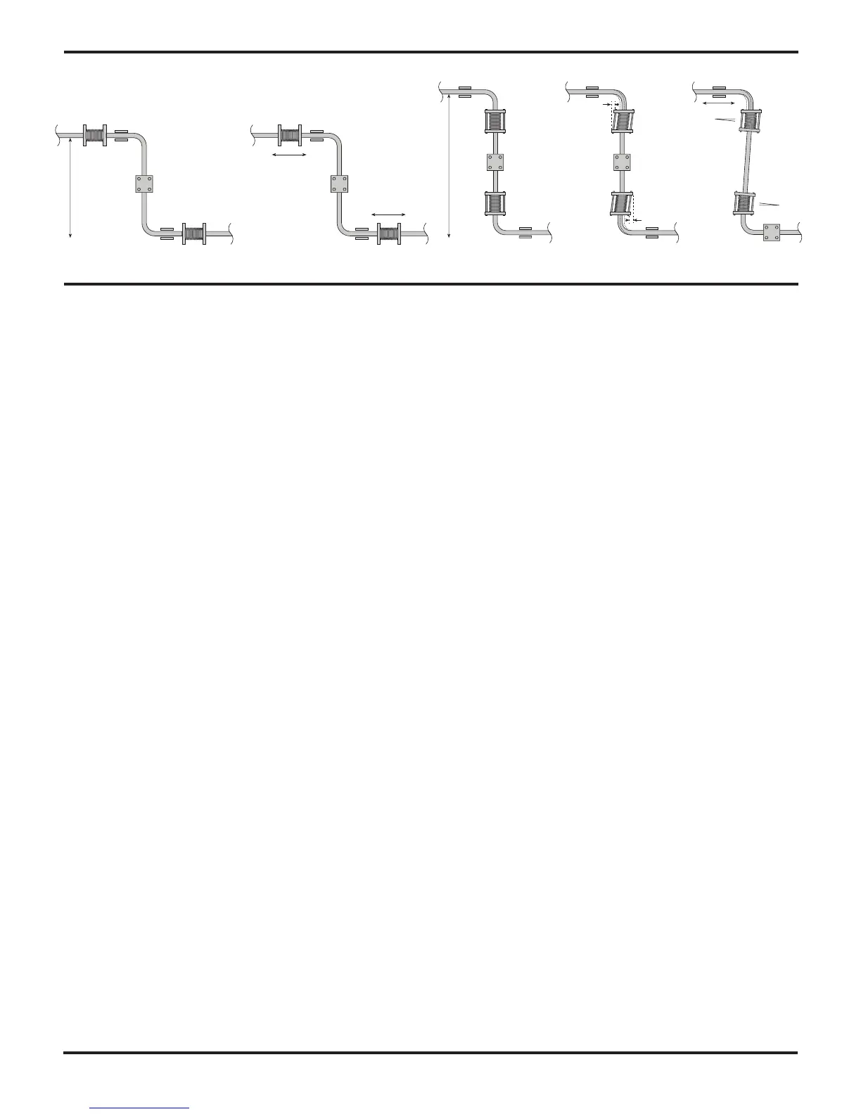
Thermal expansion:
Short
distance
Fixing point
Axial movement
Axial movement
Guides
Guides
Guides
Guides
Limit rods
Limit rods
Fixing point
Medium
distance
Small
lateral
movement
Small
lateral
movement
Large
lateral
movement
Large
lateral
movement