5
Pressure Adjustment,
Spring or Air
Pressure
Pilot
Pressure Diaphragm
Downstream
Pressure
Sensing Line
Orifice
Main Valve
Main Diaphragm
Control Pressure
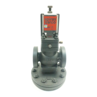
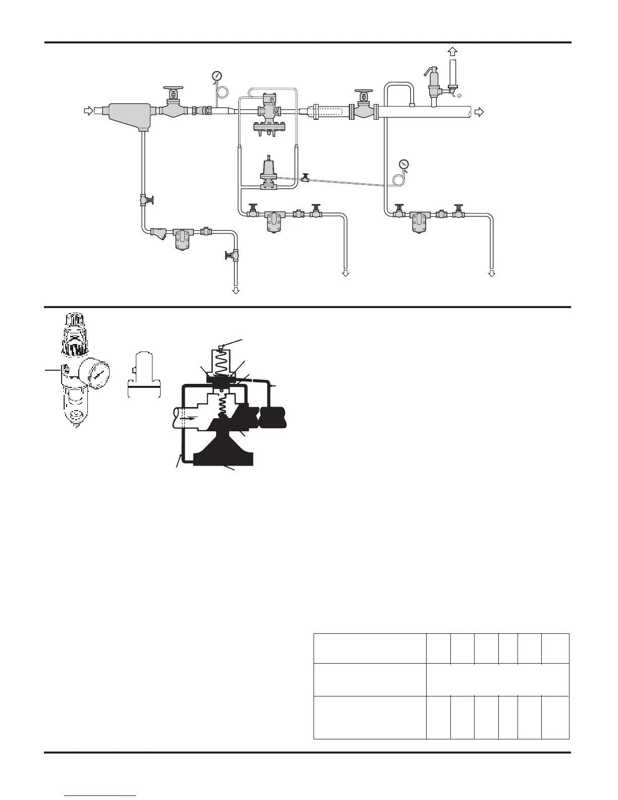
How the 25P & 25PA Work
Normal positions before start-up are with the main valve
closed and the pilot valve held open by spring force or
air pressure. Entering steam passes through the pilot
valve into the main diaphragm chamber and also out
through the control orifice. As flow through the pilot
valve exceeds flow through the orifice, control pres-
sure increases in the diaphragm chamber and opens the
main valve. As steam flows through the main valve, the
increase in downstream pressure feeds back through the
pressure sensing line to the underside of the pressure
diaphragm. When the force below that diaphragm bal-
ances the compression force of the spring above it, the
pilot valve throttles. The control pressure maintained in
the main diaphragm chamber positions the main valve to
deliver just enough steam for the desired delivery pres-
sure. Adjustment of the spring or air pressure above the
pressure diaphragm changes the downstream pressure
set point. When steam is no longer required, the sensing
line pressure increases closing the pressure pilot and the
control pressure bleeds back through the control orifice.
This allows the main valve to hold the desired reduced
pressure, and it may close tight for a dead-end shutoff.
Start-up
1. First make certain that all stop valves are closed.
2. Remove pilot spring cover then turn the pressure pilot
adjustment (2D) counter-clockwise until spring is slack.
Make certain spring remains in vertical position and
centered in its retainers.
Air loaded PA pilots must have no air pressure
supplied to them.
3. Open stop valves in the following order:
a. Open stop valve ahead of steam trap on steam
supply line. This will insure water free steam at the
regulator inlet when put into operation.
b. Open small gate valve on pressure sensing line.
c. Slowly open inlet stop valve.
4. Slowly adjust pilot spring at (2D) turning clockwise until
reduced pressure required is indicated on pressure
gauge downstream of valve.
5. Once the system has stabilized itself, slowly open
down-stream isolation valve. It may be necessary
to make re-adjustment of pilot spring (2D). Replace
spring cover then tighten adjustment locknut.
6. Important ––Retighten all pilot flange connections to
insure steam tight joints.
7. Air Loading PA Pilot requires air loading as indicated
in the following table.
Hook-up for Remote Operation of
25 PRM Pressure Reducing Valve
Float &
Thermostatic
Steam Trap
Float &
Thermostatic
Steam Trap
Float &
Thermostatic
Steam Trap
Strainer
Strainer
Safety
Valve
Steam
Supply
Moisture
Separator
Main
Control Valve
Remote
Pressure
Pilot
Limit pilot to 15 ft.
drop below main valve
and drain all sup-
ply tubing. If pilot is
mounted above main
valve, pilot line drip
traps can be elimi-
nated. For longer dis-
tance an air loaded
pilot should be used.
Drip
Pan
Elbow
Reduced
Steam
Pressure
Check
Valve
Check
Valve
Check
Valve
Noise Diffuser
(if required)
5/16” Copper
Tubing or 1/4” Pipe
1/2” Pipe
Desired Outlet Steam
5 10 25 50 75 100
Pressure P2 psig
Inlet Pressure
P1 psig
Approximate 11 16 31 56 80 102
Air Set Pressure to to to to to to
psig 13.5 16.8 33.5 58 81 103
10 psig to 100 psig
MPC2
Filter Regulator
Air
Pilot