Valve Sizes 1/2” Thru 4”
Inspecting and Replacing Main Valve
Diaphragms (Refer to Figs. 5, 6, 7, and 9)
1. Unscrew copper tubing connection at (G).
2. Remove main valve diaphragm bolts (1C).
3. This will allow the lower diaphragm case to be
removed.
4. The 2 metal diaphragms (1H) should be inspected to
insure that they have not become distorted or possibly
fractured as a result of abnormal operating conditions.
5. At the same time any accumulation of dirt or foreign
material should be removed from the diaphragm case.
6. The valve stem should also be checked to make sure
it is free to move and that there is no scale or foreign
material lodged in the guide bushing (1F).
7. Before reassembling diaphragms in 1/2” thru 4”
sizes, main valve head must be in place and head
in a closed position with the return spring and
main valve cover.
8. Make certain pressure plate (1G) is set properly.
(Refer to Fig. 5.)
9. Care should be taken in centering the diaphragms
properly and equalizing bolt take-up uniformly.
6” Valve Only
Inspecting and Replacing Main Valve
Diaphragm, Seat, and Head Assembly (Refer
to Fig. 8)
Diaphragms
1. Unscrew copper tubing connections (G) to lower dia-
phragm chamber.
2. Remove main valve diaphragm bolts (1C) and drop
lower diaphragm case.
3. The 2 metal diaphragms (1H) should be inspected and
replaced if they have become distorted or fractured.
4. Clean any accumulation of dirt from the diaphragm
case and orifice (H).
Servicing the Main Valve Head and Seat
5. Loosen the diaphragm plate set screw and remove
the diaphragm plate (1G).
6. Remove the top cover bolts (1A) and cover.
7. Remove the stem and head assembly from the valve.
Inspect the head and seat for wear.
8. Check the body erosion around the seat ring.
9. Replacement seats and heads should be lapped in,
and minor wear can be corrected by lapping with 400
grit compound.
10. On re-assembly be sure diaphragm plate (1G) is set
and set screw securely tightened.
NOTE: For replacement parts refer to Spirax Sarco
Replacement Parts Reference Guide.
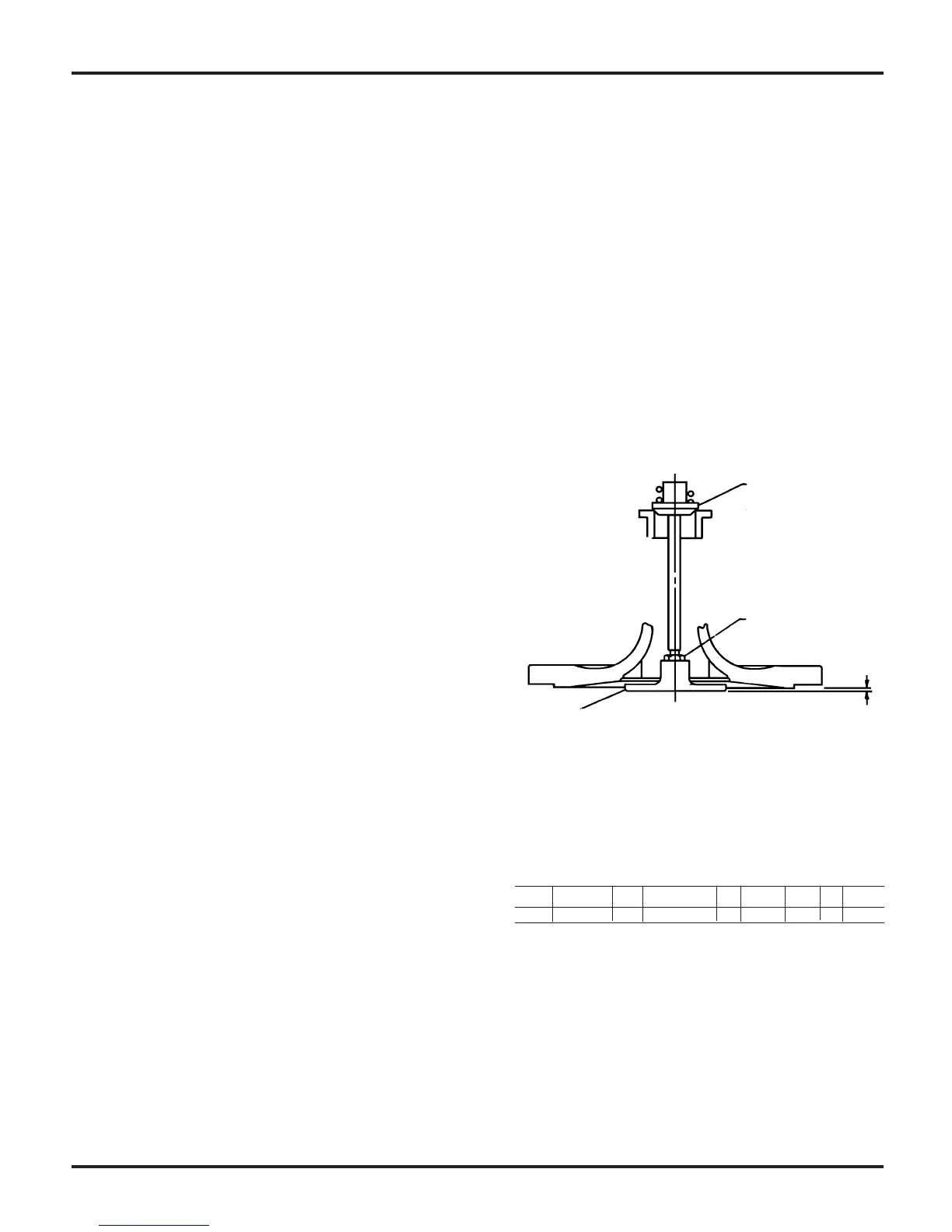
Fig. 5––Note in 1/2” and 4” sizes, top of valve must be
completely assembled and head must be on seat when
measuring dimension “A” and when re-assembling
diaphragms.
Size 1/2” & 3/4” 1” 1-1/4 & 1-1/2” 2” 2-1/2” 3” 4”
Dim. A 1/16” 5/64” 3/32” 1/8” 13/64” 13/64” 1/4”
Head on Seat
Adjustment
& Locknut
Pressure Plate
1G
8