12
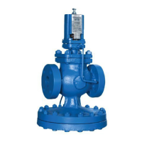
Pressure
control
pipe
Small bore
drain
Strainer with 100 mesh
stainless steel screenSeparator
Steam
supply
Spiratec
sensor
chamber
Float type
steam trap
Pressure
reducing valve
DP17 and DP17E
0.9 m, (3 ft) or 15 pipe
diameters clear on either side
See Section 3.6, page 13.
Downstream isolating valve to
provide no-load conditions for
setting pressure reducing valve
Safety
valve
Discharge
pipe
Ball valve
Check
valveStrainer
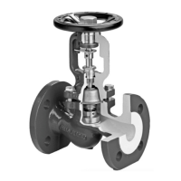
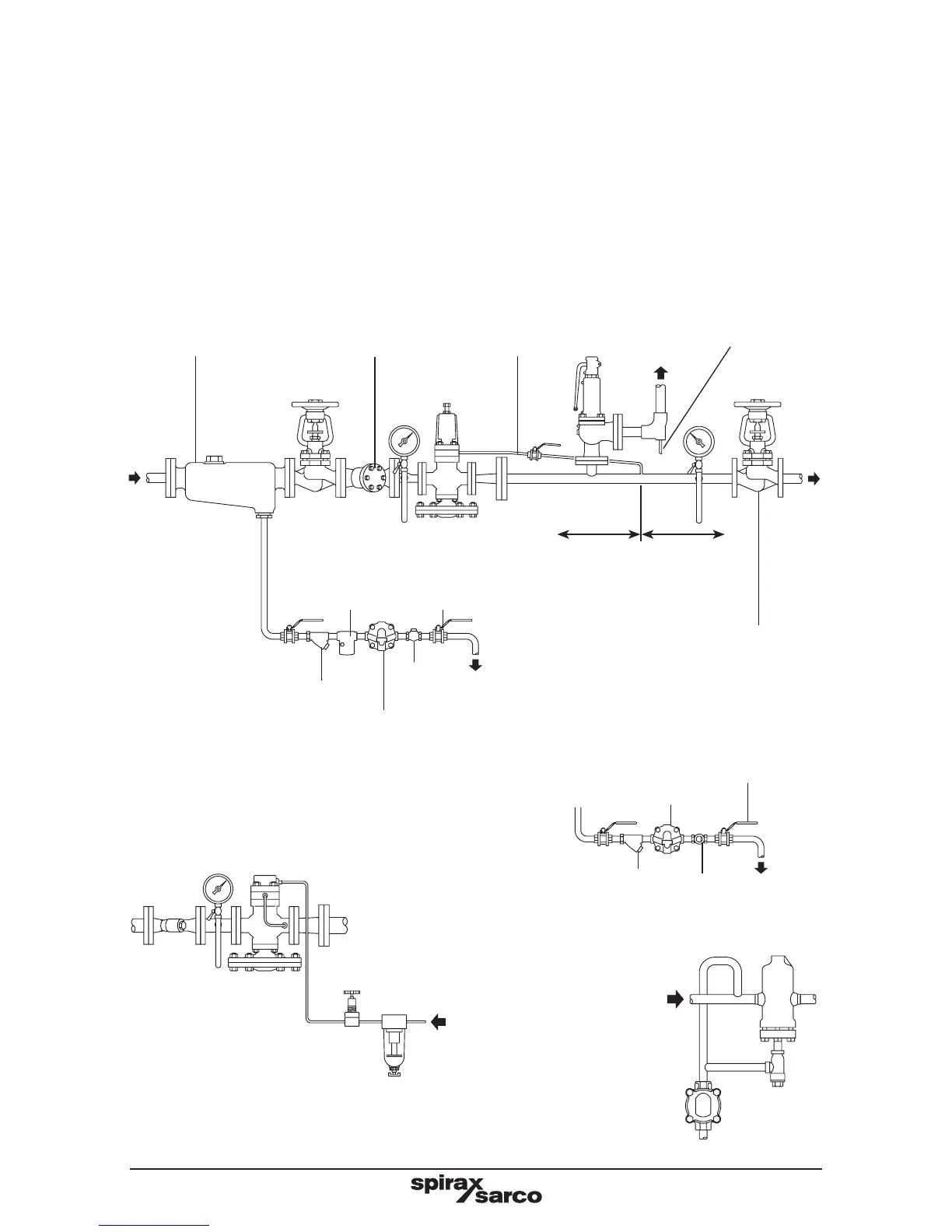
3.2 Fitting (Figs. 4, 5 and 6)
The valve should always be fitted in a horizontal pipeline with the main diaphragm chamber
below the line (Fig. 4). To meet high capacities or widely varying loads, or where stand-by
facility is required, two or more valves may be used in parallel (Fig. 5). For pressure turndown
in excess of 10 to 1 consideration should be given to using the two valves in series. To
avoid instability pipework volume between the valves should be equivalent to at least 50
pipe diameters in length of the intermediate correctly sized pipework. To ensure adequate
drainage of the space between the two reducing valves a trap set should be fitted as shown
in Fig. 6.
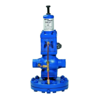
Separator
Compressed
air
Fig. 4 Recommended installation
Installation for
compressed air
(DP17G and DP27G)
Compressed
air trap
DP17R
Compressed
air
Regulator
Filter
Float type
steam trap
Alternative for
draining separator
Strainer Sight glass
Ball valve