14
3.7 Protection from dirt
The valve should be protected by a pipeline strainer with 100 mesh screen. The strainer
should be fitted on its side to prevent the accumulation of water. The strainer screen should
be examined and cleaned at regular intervals.
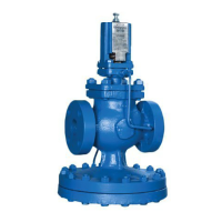
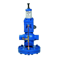
3.8 Pressure control pipe
For applications that require closer control, improved stability or maximum capacity condition
the internal pressure control pipe should be replaced by an external pressure control pipe
as follows:
Remove the internal pressure control pipe assembly.
The resulting " BSP tapping in the side of the body should be blanked using the plug
provided in the linen bag attached to the valve (which also contains the fitting instructions).
The other " BSP tapping in the side of the pilot valve chamber, should be blanked off using
the plug fitted in the tapping provided on the front of the pilot valve chamber. Into this latter
tapping, fit the brass compression fitting with brass compression ring which is also contained
in the linen bag. This is suitable for the fitting of 6 mm O/D pipe. If suitable pipe is not
available the compression fitting can be removed and ¼" nominal bore steel pipe screwed
directly into the pilot valve chamber.
The pressure control pipe should be connected into the top of the reduced pressure main
at a point where in either direction there is a length of straight pipe uninterrupted by fittings
for at least 1 m (3 ft) or 15 pipe diameters whichever is the greater. It should be arranged
with a positive fall so that any condensate can drain away from the DP17. Where the size
of the reduced pressure main makes it difficult to maintain a fall when entering the top of
the main, the pressure control pipe may be connected in the side of the main.
3.9 Pressure gauges
It is essential to fit a pressure gauge on the upstream and downstream side so that the
valve can be properly set and monitored.
3.10 Bypass
Information regarding bypasses:
It may be necessary to ensure that primary fluid flow continues in the event of the main
control failing. This is often achieved by fitting a bypass around the control valve assembly.
A better option is a duplex valve assembly, installed in parallel with the main valve, as a
manual bypass cannot accurately control pressure/flow/temperature without constant
manual supervision. Conversely, a duplex control station will provide proper control, should
the main valve ever need to be removed.
Although not recommended, if a manual bypass valve is fitted, the bypass valve flow
coefficient (K
vs
) should be the same as, or near to that of, the control valve. This means
that the manual valve and control valve could have different connection sizes. The bypass
valve should also be capable of throttling not just isolating, to reduce wear on the valve
when in service and to facilitate manual control.
Ideally, any bypass pipework should be arranged either above or alongside the main
assembly. On steam systems, it should never be below it.