IM-S02-13-IN Issue 13 7
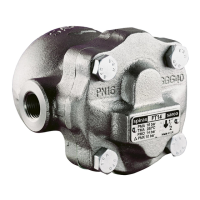
FT14 Ball Float Steam Trap ½" (DN15) to 1" (DN25)
3. Installation
Note: Before actioning any installation observe the 'Safety information' in Section 1.
Refering to the Installation and Maintenance Instructions, name-plate and Technical
Information Sheet, check that the product is suitable for the intended installation.
3.1 Check materials, pressure and temperature and their maximum values. If the maximum
operating limit of the product is lower than that of the system in which it is being fitted,
ensure that a safety device is included in the system to prevent overpressurisation.
3.2 Determine the correct installation situation and the direction of fluid flow.
3.3 Remove protective covers from all connections and the protective film from all
name-plates, where appropriate, before installation on steam or other high
temperature applications.
Installation note:
- If the trap is to discharge to atmosphere ensure it is to a safe place, the discharging
fluid may be at a temperature of 100 °C (212 °F).
- The trap must be fitted with the float arm in a horizontal plane so that it rises and
falls vertically, therefore the arrow on the name-plate must point downwards.
- Unless specified, traps will be supplied with horizontal connections and
with right to left flow (R-L). Traps can be supplied with vertical connections with
flow from top to bottom or horizontal connections with flow from right to left (R-L) or
left to right (L-R).
- The connection orientation can be changed on site by undoing the four cover bolts and
moving the cover to the preferred orientation. A new gasket must always be fitted.
- Minimum withdrawal distance to remove cover is 105 mm (4.13").
Installation of the manually adjustable needle valve (SLR - steam lock release feature)
3.4 The manually adjustable needle valve is fitted to all float traps where a suffix 'C' is hard
stamped on the name-plate e.g. FT14-10C. 'C' = Combined steam lock release feature
and thermostatic air vent.
3.5 Check if the application requires the manually adjustable needle valve for correct
operation. The manually adjustable needle valve should only be used to prevent 'steam
locking' and therefore is designed to pass only a small amount of steam.
3.6 The manually adjustable needle valve will be dispatched, pre-set to a partial bleed
condition. The unit should be screwed clockwise to close and anticlockwise to open.
When required the SLR should be used as a controlled continuous bleed, it is not
recommended that the SLR be left in the fully open condition as this may lead to
premature trap failure and more frequent maintenance schedules.
Warning
The cover gasket contains a thin stainless steel suppor t ring which may cause physical injur y
if not handled and disposed of carefully.
Please consult Spirax Sarco should further information be required.