Spirent C1 and C2 Installation Instructions
System Description
12 | Spirent C1 and C2 Installation Instructions
PN 71-008959 Rev A April 2020
SPT-C1 4 x BroadR-Reach
®
(NIC-43)
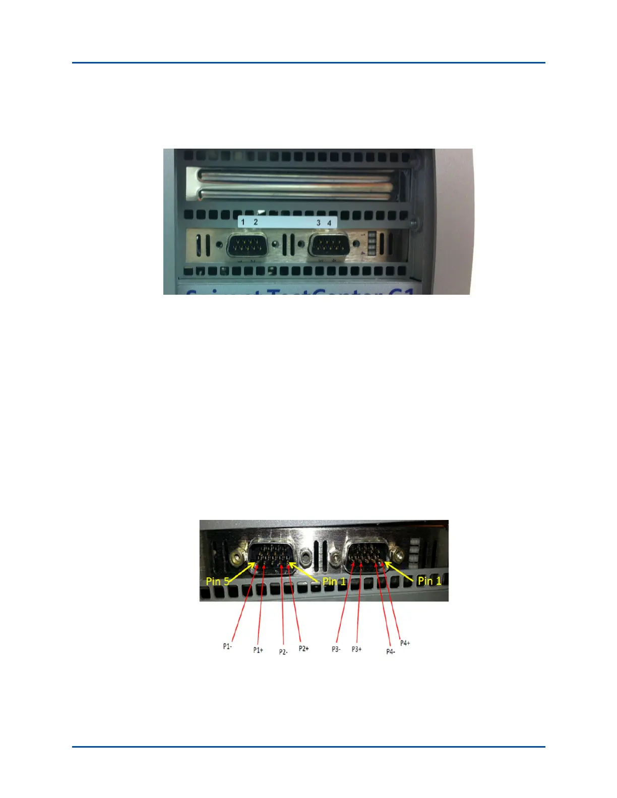
The connector panel is shown in Figure 5.
Figure 5. SPT-C1 4 x BroadR-Reach Connector Panel (NIC-43)
The network data cables (customer supplied) connected to these ports must be as follows:
• Ethernet CAT-5 cable for the management port (Eth0)
• Four test ports (1-4)
• The supported wiring is 1 pair of up to 15m UTP cabling for each port. Any
wiring from the UTP cable to the DE9F connector should be of the shortest length
possible to maintain signal integrity.
• Each DE9M connector is wired for two BroadR-Reach ports. The pinout for the
connectors is:
Port 1 signals are on the left DE9 pins 1 and 2
Port 2 signals are on the left DE9 pins 4 and 5
Port 3 signals are on the right DE9 pins 1 and 2
Port 4 signals are on the right DE9 pins 4 and 5