Spirent C1 and C2 Installation Instructions
System Description
Spirent C1 and C2 Installation Instructions | 13
PN 71-008959 Rev A April 2020
SPT-C1 2 x 10GbE and 4 x 1GbE (NIC-27 and NIC-33)
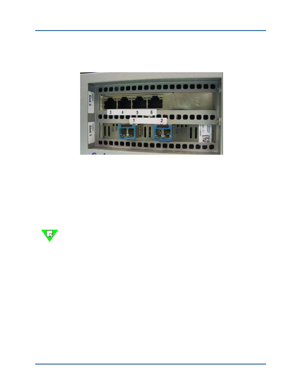
The connector panel is shown in Figure 6.
Figure 6. SPT-C1 2 x 10GbE and 4 x 1GbE (NIC-27 and NIC-33)
The network data cables (customer supplied) connected to these ports must be as follows:
• Ethernet CAT-5 cable for the management port (Eth0)
• Depending on the NIC configuration, the following for the test ports:
• Two test ports (1 and 2)
– Fiber: LC Fiber Optic connector, Multi-Mode Fiber (62.5um or 50um) cable.
• Four test ports (3-6)
– Copper: RJ45 connector, Ethernet CAT-5 cable.
Note: The timestamp circuitry between the two NICs is synchronized via firmware.
Therefore, when generating and analyzing traffic between the 10G and 1G NIC ports, the
latency measurements are not as accurate as traffic generated and analyzed between ports
on the same NIC.