SAFEGUARD POWER SOLUTIONS
WORKING PRINCIPLE
When the utility power is normal, the UPS will transfer the utility power to downstream application.
During a power outage or when the utility power is below 92v or above 138v, the UPS will transfer to
inverter mode.
While in inverter mode, the UPS will monitor flow and temperature sensor (if purchased). When flow
sensor detects a demand for water, it will turn on power output to downstream application. When the
temperature senses 37deg f (+/- 2 deg f) or below, it will also override the UPS to turn on AC output. If
flow sensor does not detect a flow or if temperature is above 37 deg f, the UPS will be in standby mode.
For non-flow applications, unplug (temp.flow) port in front of inverter to allow flow sensing bypass. For
this operation, whenever utility power is lost, the UPS will provide continuous power to downstream
application immediately.
MOUNTING AND INSTALLATION
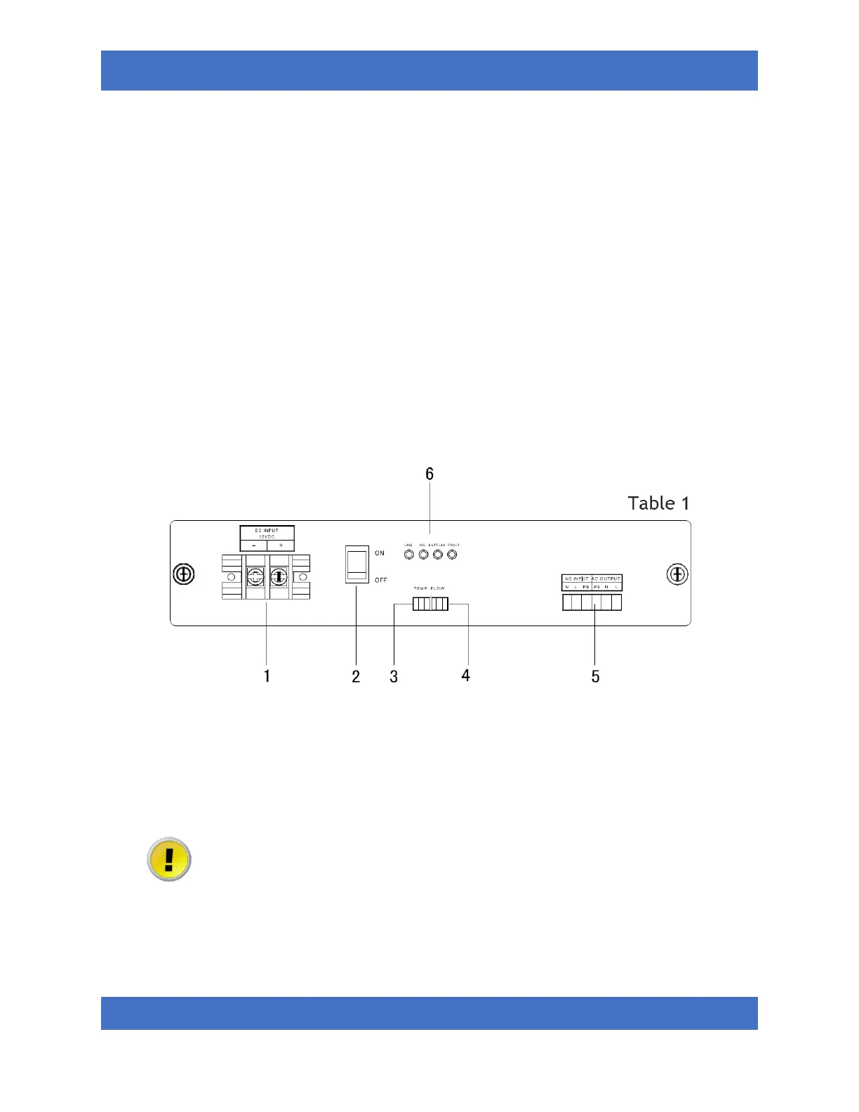
• FRONT PANEL OF UPS
1.
DC input connector bar (Connected to the battery)
2.
Toggle power switch
3.
Temperature dry contact*
4.
Flow dry contact*
5.
Input/output socket
6.
Indicator lamp
Note that when the toggle power switch is in the “ON” position, voltage may still be present at
the output terminals even when the input terminals are disconnected from power. DO NOT
transport or attempt to make connections to the terminals when the toggle switch is in the
“ON” position.
*Connected by default, disconnect for no-flow installation only.