SAFEGUARD POWER SOLUTIONS
At any time, the UPS detects overload or under/over voltage as indicated by the LED display or
chirping alarm, it will attempt delay restarts. Once such issue is resolved, i.e., battery charge is
normal or load is under 350w, the UPS will automatically restart and remove any fault
indicators.
FLOW SENSOR INSTALLATION
• NOTE: Before installing the flow sensor, make sure water is shut off at the cold-
water supply side.
• Once water pipe is disconnected, some water will drip out of the pipe. Place a bucket or
towel directly under the disconnect point of the water pipe to catch any dripping.
• Flow sensor should be installed in the cold-water piping with the arrow pointing in the same
direction as the cold-water flow (towards the tankless water heater) and in the horizontal
(preferred position) with the 4 screw heads of the sensor on top pointing upward. The flow
sensor can also be mounted vertically. However, in this orientation, when water flow is less
than 0.5gpm, the flow sensor may not be able to open the mechanical flap inside to activate.
• The included flow sensor will require two (2), not provided, ¾” Female BSP “G” Thread
Adapters to transition from G Thread to desired piping (PEX, CPVC, Copper, NPT Etc.)
o Ensure Female Hose Thread Adaptors utilize proper sealing gaskets (washers).
o Make sure to never over-tighten the adapters to the flow sensor. It is also critical to
align the threads correctly to avoid stripping of the threads on the flow sensor.
o If flow sensor is installed outdoors, please make sure it is properly jacketed to protect
from direct sunlight and freezing conditions.
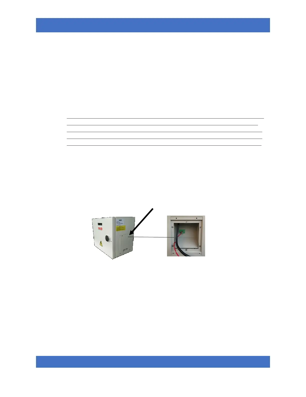
• Once Flow Sensor is installed and tested for leaks, connect the flow sensor Molex plug securely
into flow signal interface located in the wiring compartment on the right side of the unit.