Maintenance Waukesha Cherry-Burrell
Page 42 95-03009 10/2010
Disassembling the Outer Seal Assemblies
1. Using an 1/8" hex wrench, loosen the set screws (Figure 49, item A).
NOTE: The set screws are located opposite the grease fittings in the
ad
apter or end cap.
2. Remove the impeller end of the bearing housing (Figure 49, item B).
3. Remove the outer seal ring assemblies (the inner seal ring and o-
ring
s). See Figure 49 and Figure 50.
Assembling the Outer Seal Assemblies
Reverse the disassembly procedure (above) with the added step of
installing new o-rings in the seal rings.
NOTE: Figure 49 shows the seal position at the motor end. Seals at the
pump end face inward. Make sure to tighten the set screws when install-
ing the outer seal assemblies (Figure 51).
NOTE: Replace all rubber parts whenever a unit is dismantled for inspec-
tion or repair. Lubricate the rubber parts
with an approved/sanitary lubri-
cant prior to assembly.
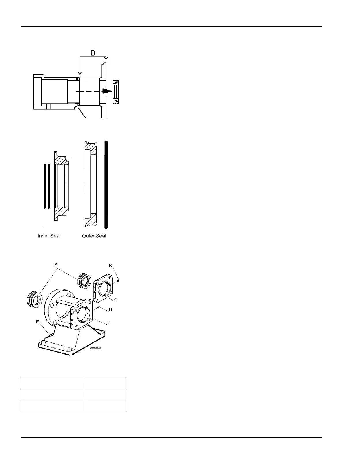
Figure 49 - Remove Set Screws
Figure 50 - Seal Configuration
Figure 51 - Outer Seal Assemblies
A. Outer Seal Assembly D. Set Screw
B. Set Screw E. Adapter
C. End Cap F. Stand