1
Table of Contents: Page:
1. General Terms 2
2. Safety Instructions 2
3. Mode of Operation 3
4. Auxiliary Equipment 4 - 5
4.1 Valve position indication - controlled valve (proximity switches)
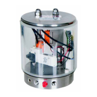
4.2 CONTROL UNIT
4.3 Adapter for CONTROL UNIT (nominal diameter DN50 - 65 and 2”- 3”)
4.4 Adapter for CONTROL UNIT (nominal diameter DN80 - 125 and 4”)
5. Installation 6
5.1 Welding Instructions
6. Dimensions / Weights 7 - 8
7. Technical Data 9
8. Materials 9
9. Maintenance 10
10. Service Instructions 11 - 13
10.1 Dismantling from the line system
10.2 Dismantling of the actuating device
10.3 Dismantling of manual actuation
10.4 Dismantling of inner parts
10.5 Replacement of seals
10.6 Installation of seals and bush bearing
10.7 Attachment of actuating device
10.8 Assembly of feedback units
10.9 Assembly of manual actuation
11. Spare Parts Lists 13
(see annex)
DSV - FZ (NC = normally closed) DN 50 - 125 - RN 01.039
DSV - FZ (NC = normally closed) inch 1”-4” - RN 01.039.1
DSV - H (manual function) DN 50 - 125 - RN 01.040
DSV - H (manual function) inch 2”-4” - RN 01.040.1
Turning actuator F/L (spring/air) for feedback unit - RN 01.076
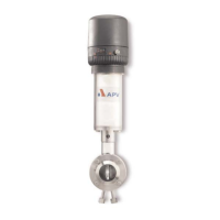
Double Seal Butterfly Valve
DSV
Operating Manual: rev. 2
DSV-UK2.qxp / 10.2005
UK