EasyManua.ls Logo

Srne HESP4840S100-H User Manual

Srne HESP4840S100-H
59 pages
To Next Page IconTo Next Page
Page #1 background imageLoading...
Page #1 background image
V2.2
USER MANUAL
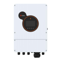
Solar Hybrid Inverter
HESP4840S100-H HESP4846S100-H HESP4850S100-H
HESP4855S100-H HESP4860S100-H

Questions and Answers:

Srne HESP4840S100-H Specifications

General IconGeneral
BrandSrne
ModelHESP4840S100-H
CategoryInverter
LanguageEnglish

Summary

Safety

How to Use This Manual

Guidance on effectively using the HESP series manual for product information.

Symbols in This Manual

Explanation of warning symbols like DANGER, WARNING, CAUTION, and NOTICE.

Safety Instructions

Critical safety guidelines for installation and operation to prevent hazards.

Production Instructions

Instructions

Overview of the HESP series solar energy storage inverter and its control algorithm.

Features

Detailed list of the HESP series inverter's capabilities, including MPPT, charging modes, and protection.

System Connection Diagram

Diagram illustrating the system components and their connections, including PV, Grid, and Loads.

Production Overview

Labeled diagram identifying all physical components and ports on the inverter unit.

Dimension Drawing

Technical drawings showing the physical dimensions and mounting hole specifications of the inverter.

Installation

Select the Mount Location

Guidelines for choosing an optimal installation location, considering environmental factors and safety.

Mount the Inverter

Step-by-step instructions for physically mounting the inverter unit to a wall.

Connection

Single-Phase Output

Details on the inverter's single-phase AC output specifications, waveform, and voltage settings.

Cable & Circuit Breaker Requirement

Specifications for cables and circuit breakers for PV, Grid, and Generator connections.

GRID & LOAD & GEN Connection

Instructions for wiring the live, neutral, and ground wires for Grid, Load, and Generator inputs/outputs.

Battery Connection

Procedure for correctly connecting the battery's positive and negative terminals to the inverter.

PV Connection

Instructions for connecting the PV strings' positive and negative wires to the inverter's PV terminals.

Grounding Connection

Guidelines for ensuring proper grounding of the inverter unit to the grounding bar.

Final Assembly

Steps to complete the installation, including closing circuit breakers and initial power-up.

Inverter Parallel

Introduction

Overview of parallel operation, including maximum units and connection requirements.

Precautions for Connecting Parallel Lines

Important warnings and guidelines for PV, battery, and load wiring in parallel setups.

Schematic Diagram of Parallel Connection in Single Phase

Diagrams showing single-phase parallel connection for 2 to 6 inverters.

Schematic Diagram of Parallel Connection in Three Phase

Diagrams illustrating three-phase parallel connection configurations for multiple inverters.

Operation

Operation and Display Panel

Description of the inverter's LCD screen, indicators, and physical buttons for operation.

Setting

Configuration options for basic, work mode, battery, grid, and advanced settings.

Time-slot Charging/Discharging Function

Functionality for scheduling battery charging and discharging based on electricity tariffs.

Battery Parameter

Detailed parameters for Lead-acid and Li-ion batteries, including voltage, current, and protection.

Communication

Dry Contact

Description of dry contact functions for RSD, generator control, and CT connection.

RS485/CAN Communication Port

Details of RS485 and CAN communication ports for BMS integration.

DIP Switch

Explanation of DIP switch functions for single and parallel inverter configurations.

WIFI Port

Information on the WIFI port for mobile monitoring and data acquisition.

USB-A Port

Function of the USB-A port for updating screen firmware.

USB-B Port

Details of the USB-B port for upper computer communication and driver installation.

Parallel Port

Description of parallel ports for communication between inverter modules.

External CT Port

Details of the external Current Transformer (CT) port and its specifications.

Fault and Remedy

Fault Code

List of fault codes, their names, impact on output, and descriptions.

Troubleshooting

Guide to diagnosing and resolving common faults based on fault codes and symptoms.

Protection and Maintenance

Protection Features

Explanation of various protection features implemented in the inverter for safety and longevity.

Maintenance

Recommendations for regular maintenance checks to ensure optimal inverter performance.

Datasheet

Related product manuals