UM1724 Rev 14 21/68
UM1724 Hardware layout and configuration
67
6.3.2 External power supply inputs: VIN and E5V
The external power sources VIN and E5V are summarized in Table 7. When the board is
power supplied by VIN or E5V, the jumpers configuration must be the following:
• Jumper on JP5 pin 2 and pin 3
• Jumper removed on JP1
Using VIN or E5V as external power supply
VIN or E5V can be used as an external power supply in case the current consumption of the
STM32 Nucleo and extensions boards exceeds the allowed current on USB. In this
condition, it is still possible to use the USB for communication, for programming or
debugging only, but it is mandatory to power supply the board first using VIN or E5V then
connect the USB cable to the PC. Proceeding this way ensures that the enumeration occurs
thanks to the external power source.
The following power sequence procedure must be respected:
Table 7. External power sources
Input
power name
Connectors
pins
Voltage
range
Max
current
Limitation
VIN
CN6 pin 8
CN7 pin 24
7 V to 12 V 800 mA
From 7 V to 12 V only and input current
capability is linked to input voltage:
800 mA input current
when Vin = 7 V
450 mA input current
when 7 V < Vin <= 9 V
250 mA input current
when 9 V < Vin <= 12 V
E5V CN7 pin 6
4.75 V to
5.25 V
500 mA -
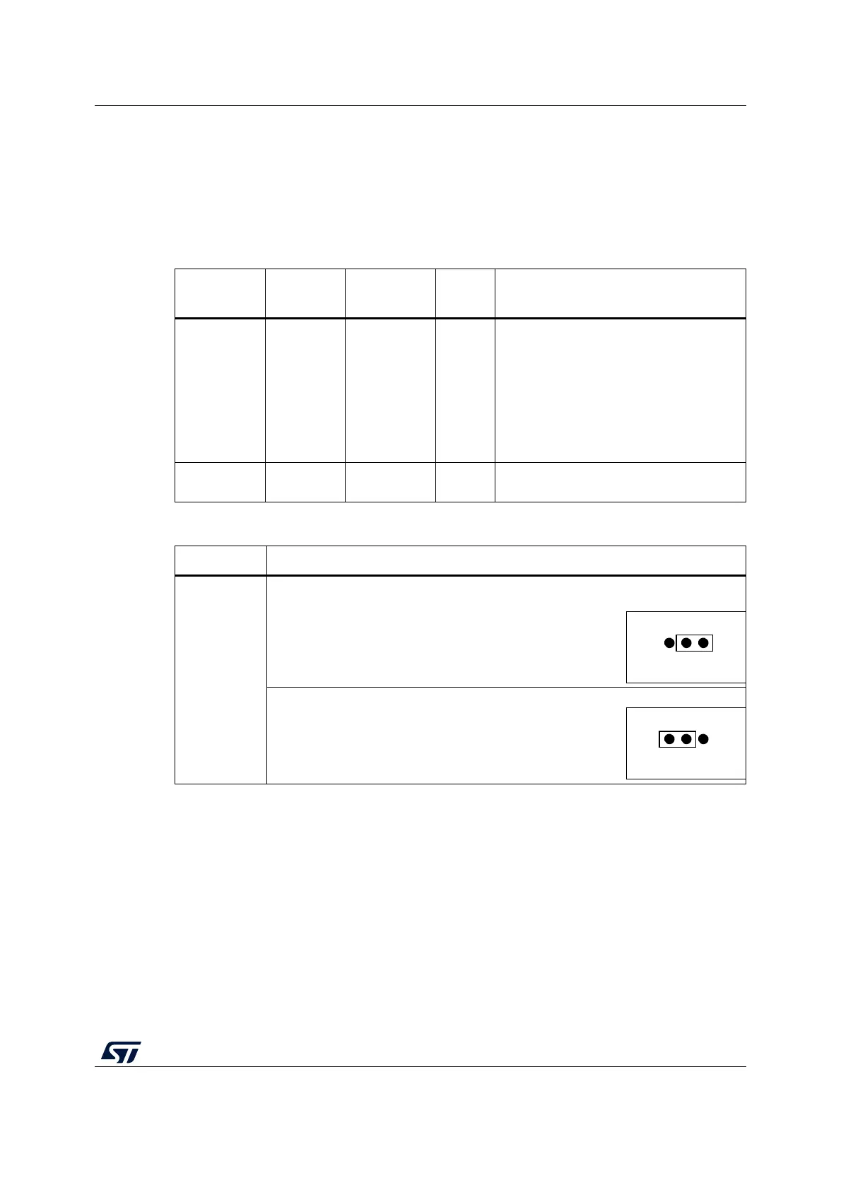
Table 8. Power-related jumper
Jumper Description
JP5
U5V (ST-LINK VBUS) is used as a power source when JP5 is set as shown below
(Default setting)
VIN or E5V is used as a power source when JP5 is set as shown below.
 Loading...