UM2502 Rev 2 17/28
UM2502 Board connectors
27
6 Board connectors
6.1 Connectors
Per convention, please refer to Table 2 for I/O Type definition:
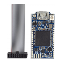
6.1.1 USB Micro-B
The CN5 USB connector is used to connect the embedded STLINK-V3MODS or STLINK-
V3MINI to the PC.
6.1.2 32-pin edge connector for STLINK-V3MODS (STM32 JTAG/SWD, VCP
and bridges)
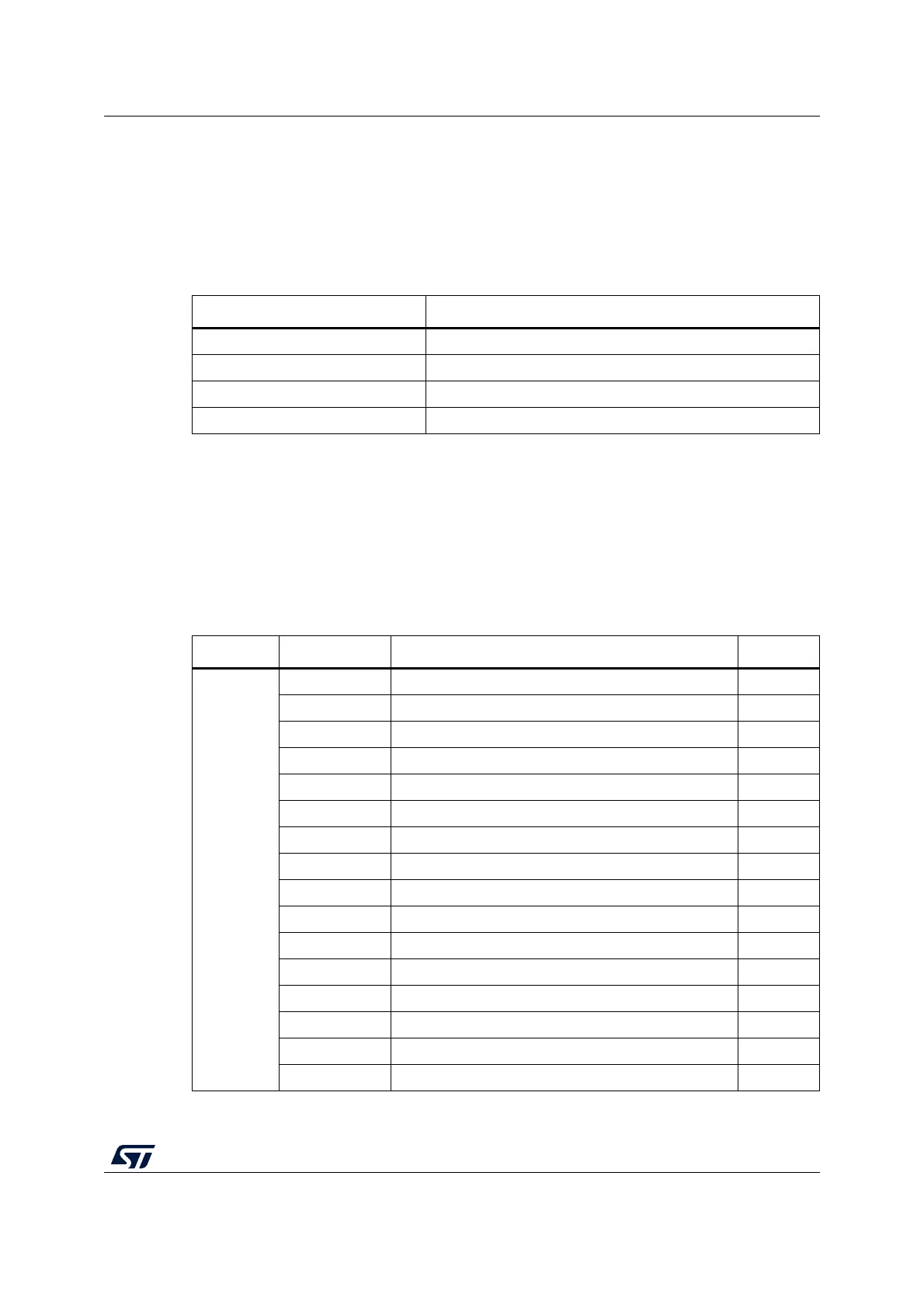
Table 2. I/O type definition
Type Definition
S Supply pin
I Input only pin
O Output only pin
I/O Input/Output pin
Table 3. 32-pin edge connector for STLINK-V3MODS
Side Pin # Pin description Type
LEFT
1 Bridge UART RX
(1)
I
2 Bridge UART CTS I
3 Bridge UART RTS O
4 T_JTMS/T_SWDIO I/O
5 GNDDetect O
6 T_JTDO/T_SWO
(2)
I
7 Bridge SPI CLK I/O
8GND S
9 Bridge CAN RX
(1)
I
10 Bridge CAN TX
(3)
O
11 Bridge UART TX
(3)
O
12 T_VCP_TX I
13 T_JCLK/T_SWCLK O
14 Bridge SPI NSS I/O
15 T_VCP_RX O
16 Bridge I2C SCL O