UM2502 Rev 2 19/28
UM2502 Board connectors
27
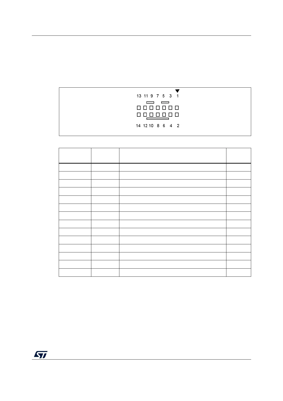
6.1.3 STDC14 for STLINK-V3MINI (STM32 JTAG/SWD and VCP)
The CN5 STDC14 connector allows the connection to an STM32 target using the JTAG or
SWD protocol, respecting (from pin 3 to pin 12) the ARM10 pinout (Arm Cortex Debug
connector). But it also advantageously provides two UART signals for the Virtual COM port.
The related pinout for the STDC14 connector is listed in
Table 4.
Figure 10. CN5 STDC14 connector (Top view)
Table 4. CN5 STDC14 connector pinout
STDC14 Pin #
ARM10 Pin
#
Pin description Type
1-Reserved
(1)
1. Do not connect on target.
-
2-Reserved
(1)
-
31T_VCC
(2)
2. T_VCC is an input for STLINK-V3MINI.
I
4 2 T_JTMS/T_SWDIO I/O
53GND S
6 4 T_JCLK/T_SWCLK O
75GND S
86T_JTDO/T_SWO
(3)
3. SWO is optional, required only for Serial Wire Viewer (SWV) trace.
I
9 7 T_JCLK O
10 8 T_JTDI/NC
(4)
4. NC means not required for SWD connection.
O
11 9 GNDDetect O
12 10 T_NRST O
13 - T_VCP_RX O
14 - T_VCP_TX I