Hardware layout and configuration UM1724
12/55 DocID025833 Rev 4
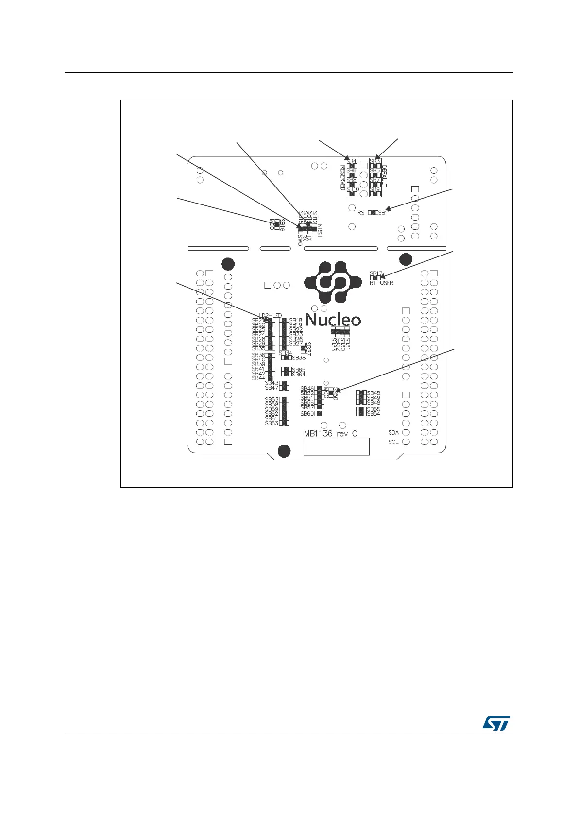
Figure 4. Bottom layout
5.1 Cutable PCB
The STM32 Nucleo board is divided into two parts: ST-LINK part and target MCU part. The
ST-LINK part of the PCB can be cut out to reduce the board size. In this case the remaining
target MCU part can only be powered by VIN, E5V and 3.3V on STMicroelectronics Morpho
connector CN7 or VIN and 3.3V on Arduino connector CN6. It is still possible to use the ST-
LINK part to program the main MCU using wires between CN4 and SWD signals available
on STMicroelectronics Morpho connector (SWCLK CN7 pin 15 and SWDIO CN7 pin 13).
4#4#4#4#
3&4&37&%
4#4#4#4#
%&'"6-5
.47
6%
86(5EXWWRQ
6%
67/,1.
5(6(7
6%
86(5/('
4#4#
45-*/,64"35
4#
45-*/,480
4#
45-*/,.$0
6%
67/,1.0&2
 Loading...