AN2739 Implementation example
9/26
Other board resources are used to interface the application:
● Audio codec: AK4343 implemented on the STM3210E-EVAL and connected to the
I2S2 interface (and to relative passive components).
● Stereo audio speaker and audio jack connected to the audio codec and implemented
on the STM3210E-EVAL.
● Joystick and key push-buttons: connected to the PG7, PD3, PG13, PG14, PG15 and
PG8 pins on the board. These push-buttons are used to control the audio stream.
● LCD screen: implemented on the STM3210E-EVAL evaluation board and controlled by
the FSMC interface.
2.2.1 Audio codec
The audio codec implemented on the STM3210E-EVAL is the AK4343 from AKM. This
codec allows digital (PCM raw data transmitted with I
2
S protocol) to analog conversion. The
audio parameterization and the codec configuration are performed through an I
2
C interface.
The codec has 36 configuration registers mainly used to:
● program the audio output (speaker or headphone) and input (analog input or digital I
2
S
data, etc.).
● enable or disable the master clock feature and, set the reference clock for internal and
sampling operations.
● set the digital volume level, the mute status and the digital filter coefficients.
The codec can operate in different modes. The modes allowed by the hardware board
implementation are listed below:
● PLL Slave mode: the internal codec clock is derived, with an internal PLL, from an
external clock. The external clock can be either the bit clock (SCK) or the channel clock
(WS) (this mode requires a high clock accuracy on SCK/WS clock).
● EXT slave mode: no PLL is used and the internal clock is derived from the MCLK input
clock (at 256 × F
S
frequency rate).
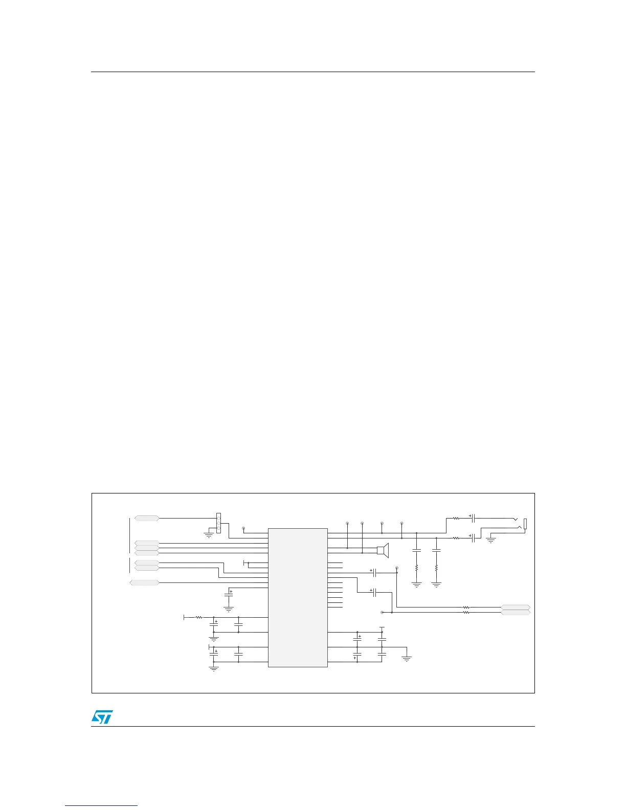
Figure 4 illustrates the hardware implementation schematic and how the codec is connected
to the STM32F103xx and the board components.
Figure 4. Audio codec hardware implementation
 Loading...


