AN4488 Rev 7 23/50
AN4488 Package
49
10
f
max(IO)out
Maximum frequency
(3)
C
L
= 40 pF, V
DD
≥ 2.7 V - - 50
(3)
MHz
C
L
= 10 pF, V
DD
≥ 2.7 V - - 100
(3)
C
L
= 40 pF, V
DD
≥ 1.7 V - - 25
C
L
= 10 pF, V
DD
≥ 1.8 V - - 50
C
L
= 10 pF, V
DD
≥ 1.7 V - - 42.5
t
f(IO)out
/
t
r(IO)out
Output high to low level fall
time and output low to high
level rise time
C
L
= 40 pF, V
DD
≥2.7 V - - 6
ns
C
L
= 10 pF, V
DD
≥ 2.7 V - - 4
C
L
= 40 pF, V
DD
≥ 1.7 V - - 10
C
L
= 10 pF, V
DD
≥ 1.7 V - - 6
11
f
max(IO)out
Maximum frequency
(3)
C
L
= 30 pF, V
DD
≥ 2.7 V - - 100
(3)
MHz
C
L
= 30 pF, V
DD
≥ 1.8 V - - 50
C
L
= 30 pF, V
DD
≥ 1.7 V - - 42.5
C
L
= 10 pF, V
DD
≥ 2.7 V - - 180
(3)
C
L
= 10 pF, V
DD
≥ 1.8 V - - 100
C
L
= 10 pF, V
DD
≥ 1.7 V - - 72.5
t
f(IO)out
/
t
r(IO)out
Output high to low level fall
time and output low to high
level rise time
C
L
= 30 pF, V
DD
≥ 2.7 V - - 4
ns
C
L
= 30 pF, V
DD
≥1.8 V - - 6
C
L
= 30 pF, V
DD
≥1.7 V - - 7
C
L
= 10 pF, V
DD
≥ 2.7 V - - 2.5
C
L
= 10 pF, V
DD
≥1.8 V - - 3.5
C
L
= 10 pF, V
DD
≥1.7 V - - 4
-t
EXTIpw
Pulse width of external
signals detected by the EXTI
controller
-10--ns
1. Guaranteed by design.
2. The I/O speed is configured using the OSPEEDRy[1:0] bits. Refer to the STM32F4xx reference manual for a description of
the GPIOx_SPEEDR GPIO port output speed register.
3. To minimize impact of process variations, IO compensation cell can be activated to reduce the overshoot during rise/fall
transitions, for maximum frequencies above 50 MHz and V
DD
> 2.4 V.
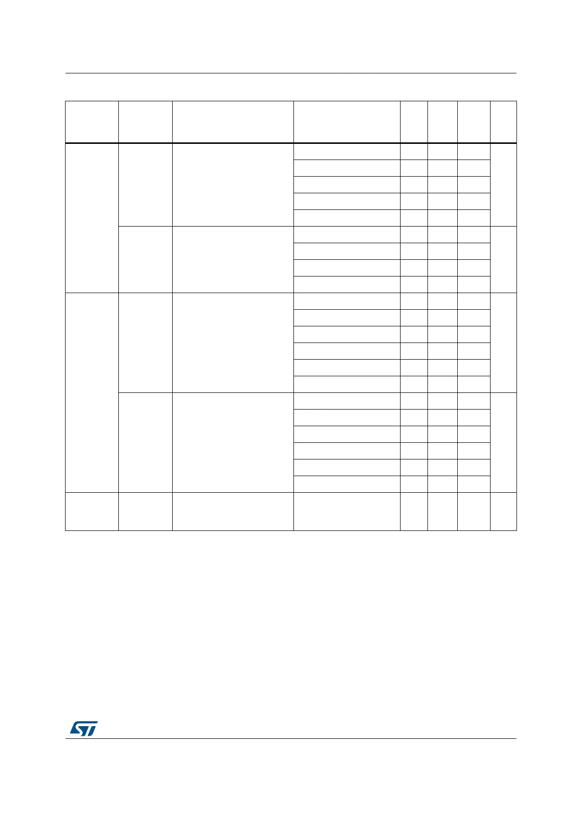
Table 4. I/O AC characteristics
(1)(2)
(continued)
OSPEEDR
y[1:0] bit
value
(1)
Symbol Parameter Conditions Min Typ Max Unit
 Loading...