AN4488 Rev 7 27/50
AN4488 Package
49
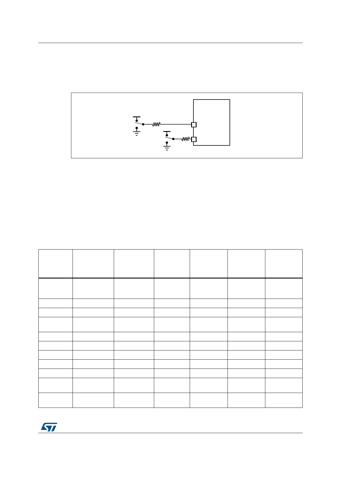
4.5 Boot pin connection
Figure 12 shows the external connection required to select the boot memory of the
STM32F4xxxx.
Figure 12. Boot mode selection implementation example
1. Resistor values are given only as a typical example.
4.6 Embedded boot loader mode
The embedded boot loader is located in the System memory and is programmed by ST
during production.
It is used to reprogram the Flash memory using one of the following serial interfaces.
The following table shows the supported communication peripherals by the system
bootloader.
06Y9
9''
670)[[[[[
%227
%227
9''
N
N
Table 7. STM32F4xxxx bootloader communication peripherals
Bootloader
peripherals
STM32F401xB/C
STM32F401xD/E
STM32F405/415
STM32F407/417
STM32F427/437
STM32F429/439
STM32F410xx
STM32F411xC/
STM32F411xE
STM32F412xx/
STM32F413xx/
STM32F423xx
STM32F469xx/
STM32F479xx
DFU
USB OTG FS
(PA11/12)
in Device mode
USB OTG FS
(PA11/12)
in Device mode
-
USB OTG FS
(PA11/12)
in Device mode
USB OTG FS
(PA11/12)
in Device mode
USB OTG FS
(PA11/12)
in Device mode
USART1 PA9/PA10 PA9/PA10 PA9/PA10 PA9/PA10 PA9/PA10 PA9/PA10
USART2 PD5/PD6 - - PD5/PD6 PD5/PD6 -
USART3 -
PB10/PB11/
PC10/PC11
- - PB10/PB11
PB10/PB11,
PC10/PC11
CAN - PB5/PB13 - - PB5/PB13 PB5/PB13
I2C1 PB6/PB7 - PB6/PB7 PB6/PB7 PB6/PB7 -
I2C2 PB3/PB10 - PB3/PB10 PB3/PB10 PF0/PF1 -
I2C3 PA8/PB4 - - PA8/PB4 PA8/PB4 -
I2C FMP1 - - - - PB14/PB15 -
SPI1
PA4/PA5/
PA6/PA7
-
PA4/PA5/
PA6/PA7
PA4/PA5/
PA6/PA7
PA4/PA5/
PA6/PA7
-
SPI2
PB12/PB13/
PB14/PB15
-
PB12/PB13/
PB14/PB15
PB12/PB13/
PB14/PB15
--
 Loading...


