AN4488 Rev 7 13/50
AN4488 Reset and power supply supervisor
49
3 Reset and power supply supervisor
3.1 System reset
A system reset sets all registers to their reset values except for the reset flags in the clock
controller CSR register and the registers in the Backup domain (see
Figure 2).
A system reset is generated when one of the following events occurs:
1. A low level on the NRST pin (external reset)
2. window watchdog end-of-count condition (WWDG reset)
3. Independent watchdog end-of-count condition (IWDG reset)
4. A software reset (SW reset)
5. Low-power management reset
The reset source can be identified by checking the reset flags in the Control/Status register,
RCC_CSR.
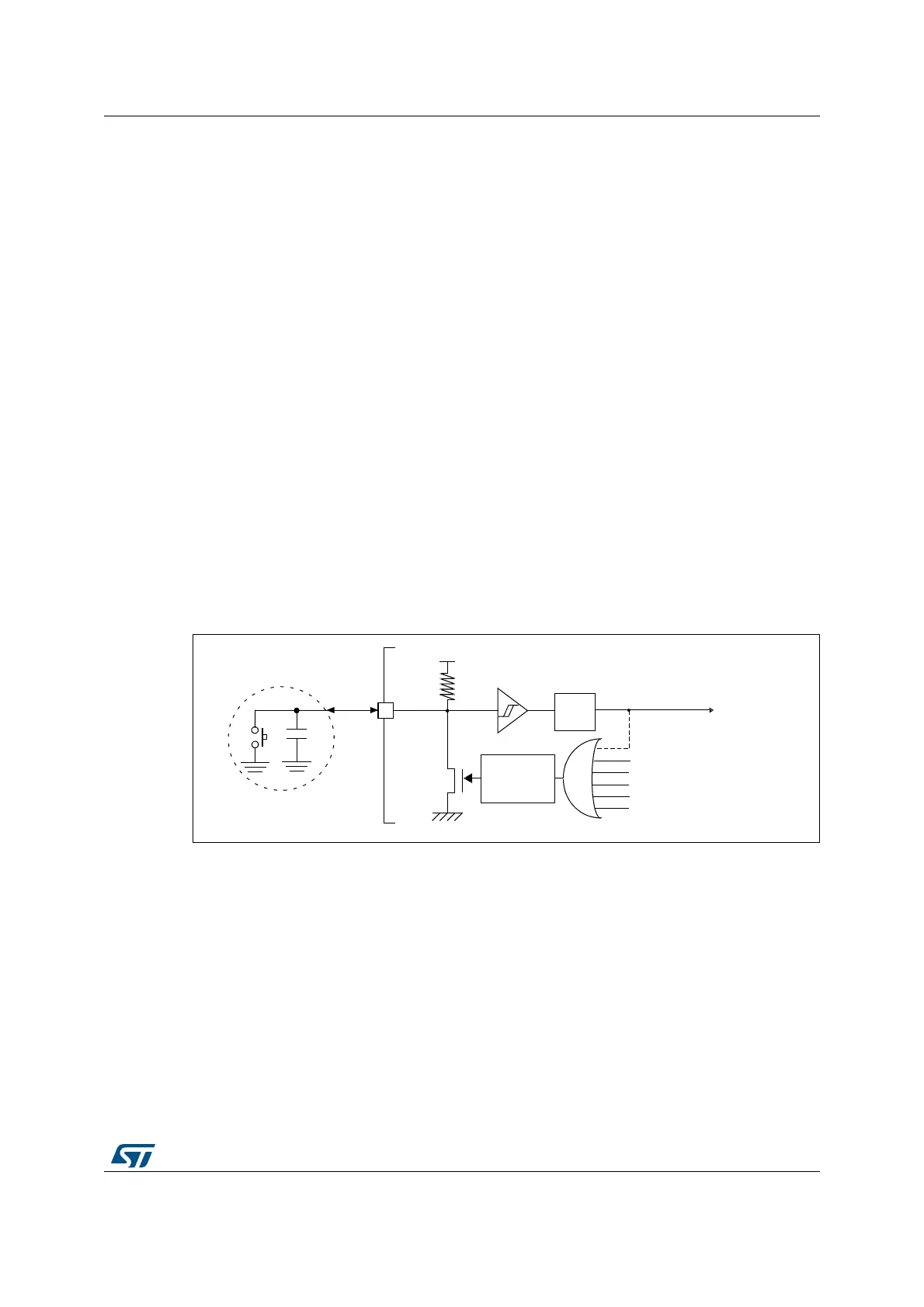
The products listed in Table 1 do not require an external reset circuit to power-up correctly.
Only a pull-down capacitor is recommended to improve EMS performance by protecting the
device against parasitic resets, as exemplified in
Figure 4.
Charging and discharging a pull-down capacitor through an internal resistor increases the
device power consumption. The capacitor recommended value (100
nF) can be reduced to
10
nF to limit this power consumption.
Figure 4. Reset circuit
3.1.1 NRST circuitry example
This example applies to STM32F410xx, STM32F411xx, STM32F412xx, STM32F413xx,
STM32F423xx, STM32F446xx and STM32F469 where PDR_ON can be connected to V
SS
to permanently disable internal reset circuitry.
Restrictions:
• PDR_ON = 0 is mostly intended for V
DD
supply between 1.7 V and 1.9V (i.e. 1.8V +/-
5% supply).
Supply ranges which never go below 1.8V minimum should be better managed by
5
38
9
''
::'*UHVHW
,:'*UHVHW
3XOVH
JHQHUDWRU
3RZHUUHVHW
PLQV
6\VWHPUHVHW
)LOWHU
6RIWZDUHUHVHW
/RZSRZHUPDQDJHPHQWUHVHW
)
([WHUQDO
UHVHWFLUFXLW
1567
DL
 Loading...


