The X4 oscillator generates the 25 MHz clock for the PHY. The 50 MHz clock for the MCU (derived from the
25 MHz crystal oscillator) is provided by the RMII_REF_CLK of the PHY.
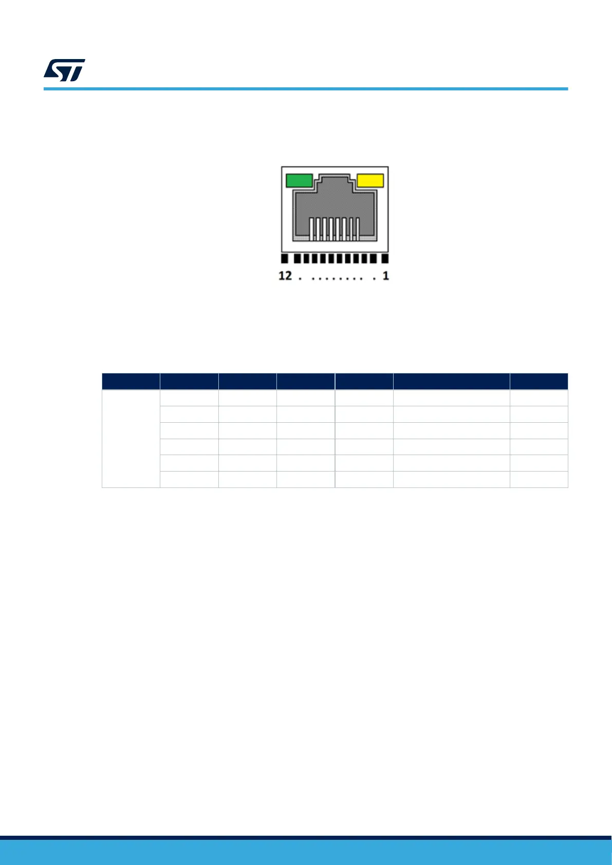
Figure 16. Ethernet RJ45 connector (CN14) front view
1. Green LED: Ethernet traffic
2. Amber LED: Ethernet connection
The related pinout for the Ethernet connector is listed in Table 20. Ethernet connector (CN14) pinout.
Table 20. Ethernet connector (CN14) pinout
Connector Pin number Description MCU pin Pin number Description MCU pin
CN14
1 TX+ - 7 NC -
2 TX- - 8 NC -
3 RX+ - 9 Yellow LED cathode -
4 NC - 10 Yellow LED anode -
5 NC - 11 Green LED cathode -
6 RX- - 12 Green LED anode -
UM3115
Ethernet RJ45 connector (CN14)
UM3115 - Rev 2
page 30/44