Electrical characteristics TIP120, TIP121, TIP122, TIP125, TIP126, TIP127
6/13
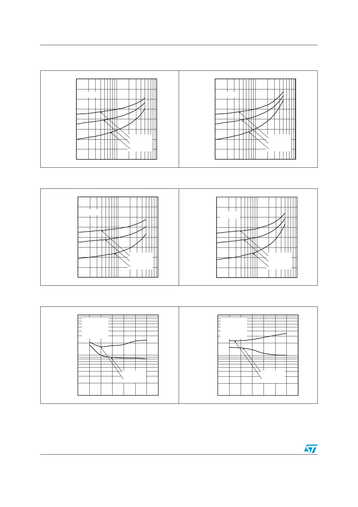
Figure 8. Base-emitter saturation voltage for
NPN type
Figure 9. Base-emitter saturation voltage for
PNP type
Figure 10. Base-emitter on voltage for NPN
type
Figure 11. Base-emitter on voltage for PNP
type
Figure 12. Switching time on resistive load for
NPN type (on)
Figure 13. Switching time on resistive load for
PNP type (on)
V
BE(sat)
1.5
1.0
0.5
0.1
I
c
(A)
1
h
FE
= 250
T
j
= -40 °C
T
j
= 25 °C
T
j
=125 °C
(V)
2.0
AM00700v1
V
BE(sat)
-1.5
-1.0
-0.5
-0.1
I
c
(A)
-1
h
FE
= 250
T
j
= -40 °C
T
j
= 25 °C
T
j
=125 °C
(V)
-2.0
AM03261v1
V
BE(on)
1.5
1.0
0.5
0.1
I
c
(A)
1
V
CE
= 3 V
T
j
= -40 °C
T
j
= 25 °C
T
j
=125 °C
(V)
2.0
AM03262v1
V
BE(on)
-1.5
-1.0
-0.5
- 0.1
I
c
(A)
-1
T
j
= -40 °C
T
j
= 25 °C
T
j
=125 °C
(V)
-2.0
V
CE
= -3 V
AM03263v1
t(ns)
100
10
0
I
c
(A)
2
Delay time
Rise time
1
3
5
4
V
cc
= 30 V
h
FE
=250
Vbeo= - 5 V
Ibon= - Ibo
AM03264v1
t(ns)
100
10
0
I
c
(A)
-2
Delay time
Rise time
-1
-3
-5
-4
V
cc
= -30 V
h
FE
=250
Vbeo= 5 V
-Ibon= Ibo
AM03265v1