Do you have a question about the STA-RITE 5P6R Series and is the answer not in the manual?
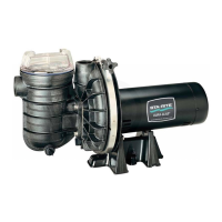
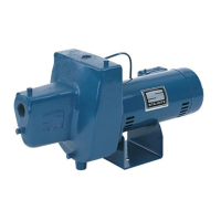
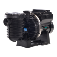
The provided manual describes the Sta-Rite 50 Hz. Max-E-Pro™ Centrifugal Pumps with Integral Trap, specifically the 5P6R Series models, designed for use with swimming pools or as general centrifugal pumps. These pumps are highlighted for their excellent performance, durability, and reliability.
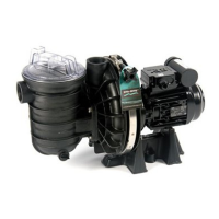
The Sta-Rite Max-E-Pro centrifugal pump is designed to circulate water for swimming pools, spas, and hot tubs. Its primary function is to draw water from the pool or spa, pass it through a filter (not part of the pump itself), and then return the filtered water to the system. The integral trap, also known as a strainer pot, is a crucial component that collects leaves, debris, and foreign matter before they can reach and potentially damage the pump's impeller. This pre-filtration step protects the pump and ensures efficient water flow. The pump is self-priming, meaning it can draw water into itself from a source below the pump level once the trap is filled with water.
Installation: Installation of the pump and its wiring should only be performed by qualified, licensed personnel. The pump mount must be solid, level, rigid, and vibration-free to minimize vibration and pipe stress. It should be located away from corrosive or flammable chemicals and have adequate ventilation to maintain the motor's ambient temperature below its maximum rating. The suction inlet height should be as close to the water level as possible, allowing for short, direct suction piping to reduce friction losses. Gate valves are recommended in both suction and discharge piping for ease of service. Proper floor drainage is also advised to prevent flooding. For threaded connections to the pump, only Teflon tape or Plasto-Joint Stik should be used; pipe dope is explicitly warned against as it can cause stress cracking. The pump's suction and discharge connections have molded-in thread stops, and users are cautioned not to screw pipes in beyond these stops.
Piping and Fittings: At least 2-inch IPS PVC pipe is recommended, with larger sizes for longer runs. Both suction and discharge pipes should be independently supported near the pump to avoid strain. Piping should start at the pump and run away from it to prevent gaps at connections. Suction pipes should never be smaller than the pump's suction connection and should be sloped slightly upward toward the pump to prevent airlocking. For flooded suction systems, gate valves in both suction and discharge pipes are necessary to prevent flooding during service. To ensure optimal efficiency, the fewest possible fittings should be used, and fittings that could cause an air trap should be avoided. Pool fittings must comply with IAPMO standards, and only non-entrapping or double suction fittings should be used.
Safety Requirements for Suction: Pump suction is a significant hazard, capable of trapping and drowning or disemboweling bathers. Therefore, strict guidelines must be followed:
Electrical Connections: Electrical work must be performed by qualified personnel. The motor must be permanently grounded to the electrical service ground using the green ground terminal and bonded to the pool structure using a solid copper conductor (No. 8 AWG or larger) connected to the external bonding lug, reinforcing rod, or mesh, and all metal parts within 5 feet of the pool. Supply voltage must exactly match the motor nameplate voltage to prevent damage and void warranty. A Ground Fault Circuit Interrupter (GFCI) must be installed in the circuit to protect users from electrical shock. Power must be turned OFF before working on any wiring.
Operation: The pump should never be run dry, as this can damage seals and cause leakage. Before starting, the pump and trap must be filled with water. In flooded suction systems, the pump will self-prime when valves are opened. For non-flooded systems, the trap cover must be removed, and the trap and pump filled with water. The trap cover handle ring should be tightened by hand only, without wrenches. Priming time varies depending on suction lift and piping length. If the pump fails to prime, check for open valves, submerged suction pipe end, and suction pipe leaks.
Routine Maintenance: The only routine maintenance required is the inspection and cleaning of the trap basket. Debris in the basket can choke off water flow. To clean the trap:
Draining and Winterizing: To drain the pump, the water level in the pool must be lowered below all inlets. The trap cover should be removed, and low-pressure air can be used to blow accumulated water from the piping. Inlet piping should be capped to keep water out. To prevent freezing damage, the trap cover and drain plugs on the tank body should be removed to drain the pump completely. The trap and basket should be cleaned, and the trap cover replaced (hand tight only). The motor must be kept dry and covered during storage. For winterizing, anti-freeze solutions (except propylene glycol) should not be used in the pool/spa system. All water must be drained from the pump and piping if freezing temperatures are expected or for long-term storage. For outdoor installations, the system should be gravity drained as much as possible, areas retaining water protected with non-toxic propylene glycol antifreeze ("RV antifreeze"), and the entire system enclosed in a weatherproof enclosure with ventilation to prevent condensation/corrosion.
Pump Service (Seal Replacement): Pump service, particularly seal replacement, should only be performed by qualified personnel. Disassembly:
Reassembly/New Seal Installation:
| Series | 5P6R |
|---|---|
| Category | Water Pump |
| Voltage | 115/230V |
| Horsepower | 1.5 HP |
| Port Size | 2 inches |
| Model | 5P6R |
| Phase | Single-Phase |
| Inlet Size | 2 inches |
| Weight | 45 lbs |
| Type | Self-priming centrifugal pump |