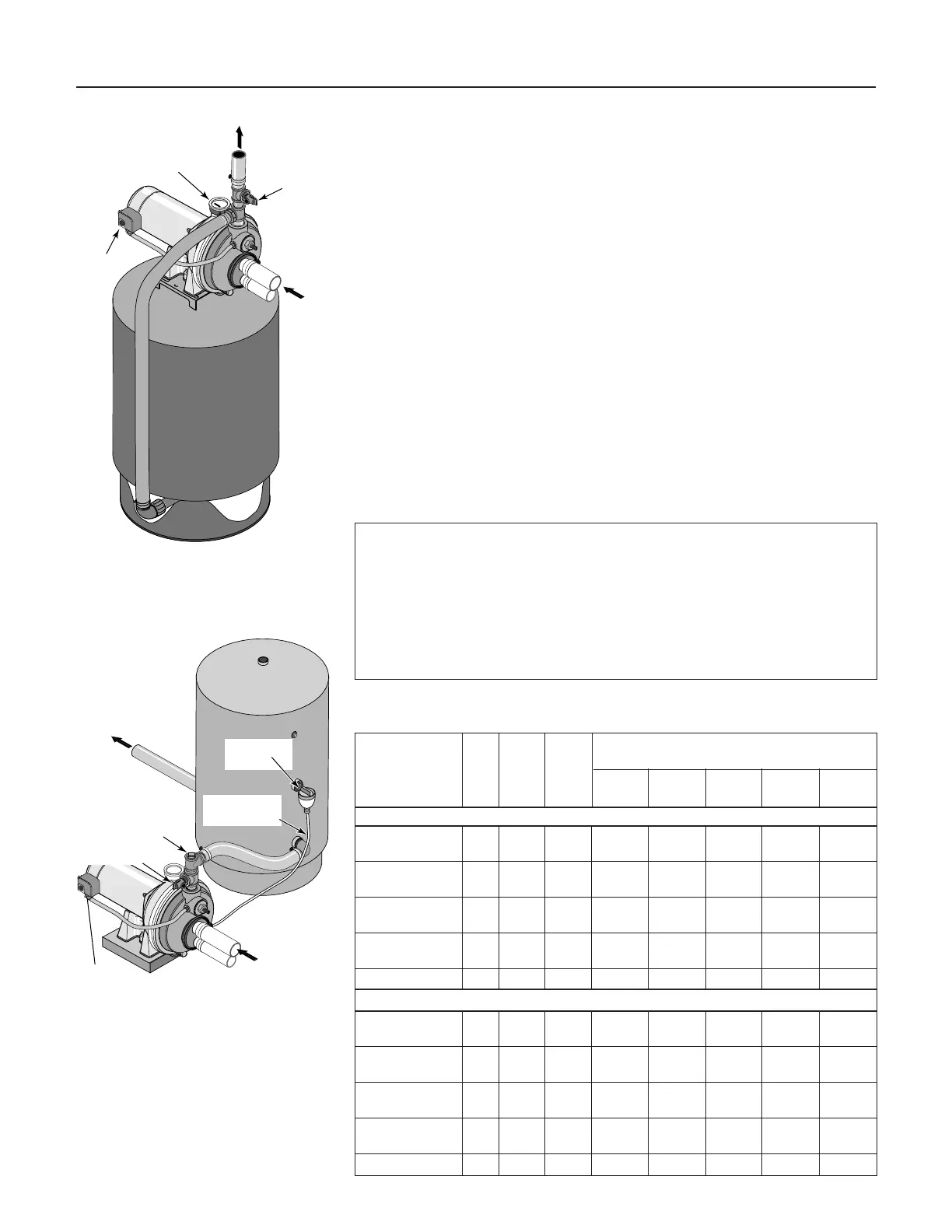
Figure 6: Pre-charged Tank
Connections
Figure 7: Standard Tank Connections
Table I: Wiring Chart – Recommended Wire and Fuse Sizes
PRE-CHARGE TANK CONNECTION (Figure 6)
If your system uses a Con-Aire (pre-charged) tank, it should be connected to
the pump as shown in Figure 6. The relief valve must be capable of passing
the entire pump capacity at 100 PSI pressure.
Check the pre-charge of air in the tank with an ordinary tire gauge. the pre-
charge is measured
when there is no water pressure in the tank.
Disconnect
power to the pump and drain the tank before checking the pre-charge. Your
pump has a 30/50 PSI switch, so the tank pre-charge pressure should be 28
PSI (that is, it should be 2 PSI lower than the cut-in pressure of the pressure
switch.
No AVC is required for a pre-charged tank; the 1/8” NPT AVC port on the
pump body should be plugged.
STANDARD TANK CONNECTION (Figure 7)
If your system uses a standard tank, connect it to the pump as shown in
Figure 7. The relief valve used with a standard tank must be capable of pass-
ing the entire pump capacity at 75 PSI pressure.
Connect the Air Volume Control (AVC) tube to the 1/8” NPT AVC port on the
pump body. Run the tubing from the pump’s AVC port to the AVC mounted
on the tank. See the instructions provided with tank and AVC for details.
Branch Distance in Feet (Meters);
Max Fuse Wire Size AWG (mm
2
)
Load Rating 0-100 101-200 201-300 301-400 401-500
Model HP Amps Amps (0-30) (31-61) (62-91) (92-122) (123-152)
115Volts:
ALB, BBLB 1/3 9.4 15 14(2) 10(5.5) 10(5.5) 6(14) 6(14)
HLB, PLB 1/3 9.4 15 14(2) 10(5.5) 10(5.5) 6(14) 6(14)
ALC, FSLC, PLC 1/2 9.4 15 14(2) 10(5.5) 10(5.5) 6(14) 6(14)
BBLC, HLC 1/2 12.2 20 12(3) 10(5.5) 8(8.4) 6(14) 6(14)
ALD, FSLD, PLD 3/4 12.2 20 12(3) 10(5.5) 8(8.4) 6(14) 6(14)
BBLD, HLD 3/4 14.8 20 12(3) 8(8.4) 6(14) 6(14) 4(21)
ALE, PLE 1 14.8 20 12(3) 8(8.4) 6(14) 6(14) 4(21)
BBLE, HLE 1 19.2 25 10(5.5) 8(8.4) 6(14) 4(21) 4(21)
ALF, PLF 1-1/2 19.2 25 10(5.5) 8/8.4) 6(14) 4(21) 4(21)
230 Volts:
ALB, BBLB 1/3 4.7 15 14(2) 14(2) 14(2) 14(2) 12(3)
HLB, PLB 1/3 4.7 15 14(2) 14(2) 14(2) 14(2) 12(3)
ALC, FSLC, PLC 1/2 4.7 15 14(2) 14(2) 14(2) 14(2) 12(3)
BBLC, HLC 1/2 6.1 15 14(2) 14(2) 14(2) 12(3) 12(3)
ALD, FSLD, PLD 3/4 6.1 15 14(2) 14(2) 14(2) 12(3) 12(3)
BBLD, HLD 3/4 7.4 15 14(2) 14(2) 14(2) 12(3) 10(5.5)
ALE, PLE 1 7.4 15 14(2) 14(2) 14(2) 12(3) 10(5.5)
BBLE, HLE 1 9.6 15 14(2) 14(2) 12(3) 10(5.5) 10(5.5)
ALF, PLF 1-1/2 9.6 15 14(2) 14(2) 12(3) 10(5.5) 10(5.5)
Sealing Pipe Joints
Use only Teflon tape or Teflon based joint compounds for making all
threaded connections to the pump itself. Do not use pipe joint com-
pounds on plastic pumps: they can react with the plastic in pump com-
ponents. Make sure that all pipe joints in the suction pipe are air tight as
well as water tight.
If the suction pipe can suck air, the pump will not be
able to pull water from the well.