This document is an owner's manual for Sta-Rite Self-Priming Centrifugal Pumps, specifically the "D" Series. It provides comprehensive information on installation, operation, and parts, along with important safety, maintenance, and warranty details.
Function Description:
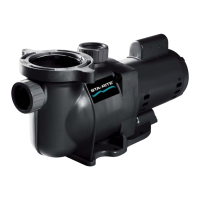
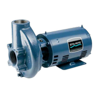
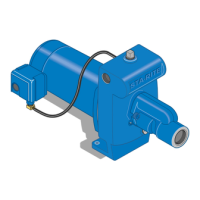
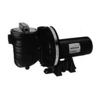
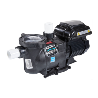
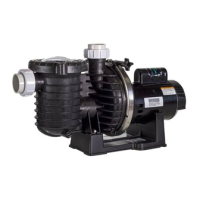
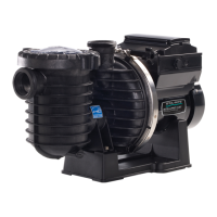
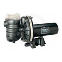
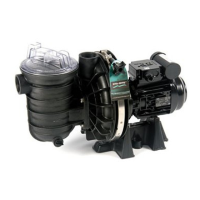
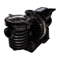
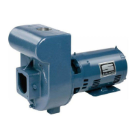
The Sta-Rite "D" Series Self-Priming Centrifugal Pumps are designed to move water efficiently. Their self-priming capability means they can draw water into the pump without needing to be manually filled with liquid each time, provided the built-in check valve functions correctly. These pumps are suitable for various water systems applications, including jet pumps, small centrifugal pumps, submersible pumps, and related accessories. They are engineered for reliable performance in residential, commercial, or agricultural settings where water transfer is required. The manual emphasizes that these pumps are designed to pump water only.
Important Technical Specifications:
The manual includes a detailed "Repair Parts" section with specific part numbers for 3 HP and 5 HP models, both single-phase and three-phase, operating at 200V, 230V, and 460V. Key components listed include:
- Motors: Available in 3 HP and 5 HP configurations, with various voltage options (200V, 230V, 460V) and phase types (single or three-phase). Specific motor part numbers are provided (e.g., C218-177 for 3 HP, 230V, single-phase).
- Impellers: Different impellers are listed for various models (e.g., C5-246, C5-247, C5-248, C5-249).
- Shaft Seal: A critical component for pump operation, with part number U109-220 for all listed models.
- Pump Body: Specific part numbers for the pump body (e.g., C76-12, C76-12C, C76-12B).
- Suction Flange Assembly: Available in different NPT sizes (1-1/2", 2", 2-1/2", 3") with corresponding part numbers (e.g., C203-22 for 1-1/2" NPT, C203-22A for 2" NPT).
- Electrical Wiring: The manual provides a "Recommended Wire and Fuse Sizes" table (Table I) based on motor HP, phase, volts, max load amps, fuse rating amps, and distance from motor to meter (up to 500 feet). For example, a 3 HP, 1-phase, 230V motor with 17.0 max load amps and 25 amp fuse rating requires 12 AWG wire for distances up to 200 feet, 10 AWG for 300 feet, and 8 AWG for 400-500 feet.
- Pressure Relief: A critical safety warning states that the pump body may explode if used as a booster pump unless a relief valve capable of passing full pump flow at 75 psi is installed in the discharge pipe.
Usage Features:
- Self-Priming: The pump is designed to prime itself after initial filling, thanks to a built-in check valve. A priming plug on the discharge tee allows for initial filling.
- Installation Guidelines:
- Location: Locate the pump as close to the liquid source as possible with a short, direct suction pipe to minimize static suction lift. Mount on a solid, level, vibration-free foundation, protected from flooding and excessive moisture.
- Piping: Both suction and discharge piping must be independently supported to prevent strain on the pump. Suction piping should have a gradual upward slope to the pump, free of air traps. A gate valve and union are recommended in the discharge line for easy removal and service.
- Electrical Connections: Emphasizes grounding the motor before connecting to power supply. Motors are factory wired for 230V operation (single-phase) or require specific connections for dual-voltage three-phase motors. Supply voltage must be within ±10% of the nameplate voltage. Wire size should follow the provided chart.
- Motor Rotation Check: For three-phase motors, the manual advises checking for clockwise shaft rotation by removing the motor end cover.
- Operation Safety: Warnings against running the pump dry (can cause overheating and seal damage) and against closed discharge (can cause hazardous pressure, explosion risk, and scalding).
Maintenance Features:
- Minimal Maintenance: Little maintenance is required beyond potential shaft seal replacement.
- Motor Lubrication: Lubricate the motor according to the motor manufacturer's instructions; periodic greasing is required for most motors.
- Pump Storage: Drain the pump to prevent freezing. Keep the motor dry and loosely covered, avoiding plastic sheeting that can trap moisture and cause corrosion. A rust inhibitor is recommended for cast iron pump liquid ends.
- Start-up After Storage: Replace drain plugs, close drain valves, ensure tight connections, and fill the pump (prime) before reconnecting power.
- Shaft Seal Replacement: Detailed, step-by-step instructions are provided for removing the old seal and installing a new one. This process involves disconnecting power, draining the pump, disassembling the motor and adapter/seal plate, carefully removing the old seal components, cleaning, and then meticulously installing the new seal, ensuring polished faces are handled with care and oriented correctly. Special tools like screwdrivers or a bearing puller may be used. The manual stresses the importance of not scratching the seal faces and using a 1" standard pipe as a press for the stationary seal half if needed. It also advises applying liquid soap to the rubber drive ring and ensuring the shaft sleeve is clean and potentially greased to prevent freezing.
- Periodic Inspection: Periodically inspect pump and system components.
- Safety Label Maintenance: Keep safety labels in good condition and replace any missing or damaged ones.