S6
INSTRUCTIONS
DIGITAL SPEEDOMETER MK2, UNIVERSAL
EN
24
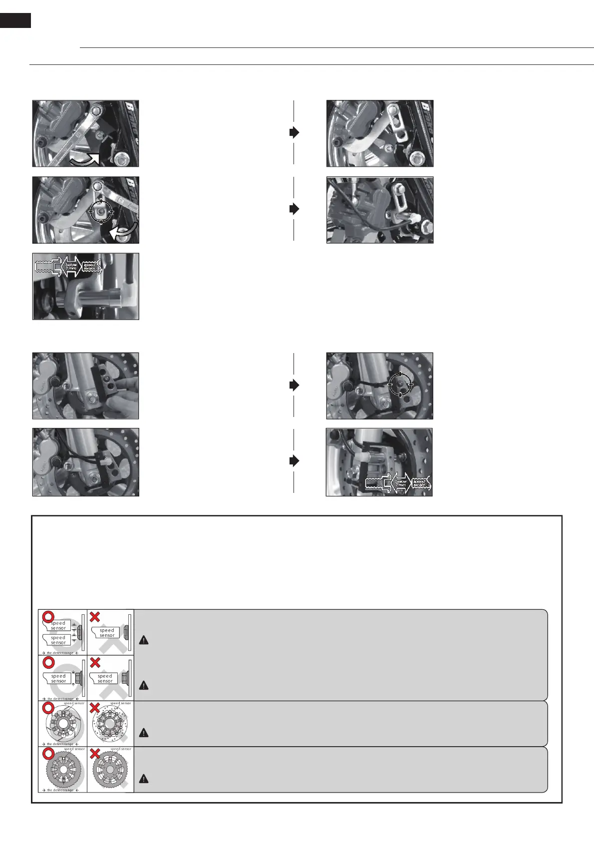
S-Type Speed Sensor Bracket Installation Instructions
L-Type Speed Sensor Bracket Installation Instructions
• Adjust the distance between
sensor and magnet to get the
best speed signal. It should be
under 2 mm.
• Loosen the screw on the caliper.
• Adjust the bracket to the proper
angle: once the speed sensor has
been installed into its bracket and
the magnets have been installed
into the screws of the brake disc,
the magnets must pass under the
sensor when the wheel turns.
• Install the S-type bracket on the
caliper.
• Install the speed sensor.
• Install the L-type bracket and the
anti-slip rubber on the front fork
and adjust them to the proper
position.
• Install the speed sensor into the
proper hole in the bracket.
• Fix the bracket to the front
fork with a cable tie, noting the
correct position of the bracket:
once the speed sensor has
been installed into its bracket
and the magnets have been
installed into the screws of the
brake disc, the magnets must
pass under the sensor when the
wheel turns.
• Adjust the distance between
sensor and magnet to get the
best speed signal. It should be
under 2 mm.
About the Active Speed Sensor Installation
The active speed sensor can be installed to pick up the speed from various metal parts:
Ex. 1: Disc screws
Ex. 2: Brake discs and gaps (Please make sure the gaps have the same width to avoid wrong signals.)
Ex. 3: Sprockets and gaps (Please make sure the gaps have the same width to avoid wrong signals.)
We recommend picking up the speed signal from the disc screws. The more sensor points there are, the better the speed accuracy. The maxi-
mum number of sensor points that the active speed sensor can detect is 60 points.
Ex. 1: Hexagon socket disc screw
Best area to pick up the signal: the edge of the screw.
Please don’t try to pick up the signal from the middle hole of the hexagon socket screw, as this may lead to incorrect signals.
Ex. 1: Hexagon screw
Best area to pick up the signal: the middle of the screw.
Some hexagon screws have a small hole in the centre. In this case, we recommend picking up the signal from the edge of
the screw like the hexagon socket screw.
Ex. 2: Disc
Best area to pick up the signal: the gaps of the disc.
Please note that this will not work when the gaps have different widths!
Ex. 3: Sprocket
Best area to pick up the signal: the gaps of the sprocket.
Please note that this will not work when the gaps have different widths!
 Loading...