ASSEMBLY INSTRUCTIONS
8
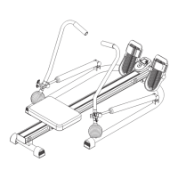
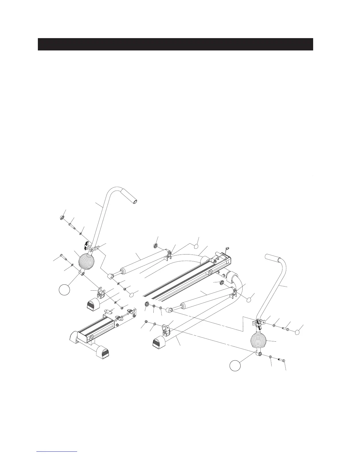
STEP 2
There is an “R” decal on the RIGHT HANDLEBAR(6), and a “L” decal on the LEFT HANDLEBAR(7). Slide
the BELLOW(24) onto the RIGHT HANDLEBAR(6). Attach the RIGHT HANDLEBAR(6) to the PIVOTING
BRACKET(3) located on the rear of the RIGHT BASE(1) with HEX HEAD BOLT(M8x1.25x45mm)(40),
WASHERS(M8)(46), and NYLOCK NUT(M8x1.25)(48). Slide the BELLOW(24) down to touch the RIGHT
BASE(1) to cover the bracket.
STEP 3
Attach the SHOCK(17) to the TENSION ADJUSTER(5) which attached on the RIGHT HANDLEBAR(6) with
HEX HEAD BOLT(M8x1.25x45mm)(40), WASHERS(M8)(46), and NYLOCK NUT(M8x1.25)(48). Press
the NUT CAPS(35) onto the HEX HEAD BOLT(M8x1.25x45mm)(40) and NYLOCK NUT(M8x1.25)(48),
including the HEX HEAD BOLT(M8x1.25x45mm)(40) and NYLOCK NUT(M8x1.25)(48) on the bottom
end of the SHOCK(17).
Repeat the above to attach the LEFT HANDLEBAR(7) and SHOCK(17) on the left side.
1
2
17
17
6
7
40
40
46
48
46
46
46
48
40
40
46
46
46
46
48
24
24
35
35
35
35
35
35
35
48
40
5
5
3
3
48
35
L
R