ASSEMBLY INSTRUCTIONS
7
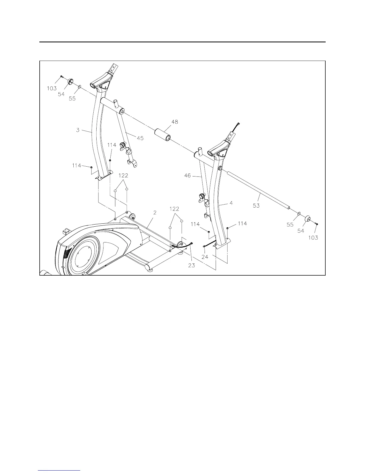
STEP 3
Connect the UPPER CONNECTION WIRE(24) in the RIGHT UPRIGHT(4) to the BASE CONNECTION
WIRE(23), then attach the RIGHT UPRIGHT(4) to the FRONT BASE(2) with the NYLOCK NUTS(M8x1.25)
(114). Do not tighten the nuts until STEP 8.
STEP 4
Attach the LEFT UPRIGHT(3) to the FRONT BASE(2) with the NYLOCK NUTS(M8x1.25)(114). Do not
tighten the nuts until STEP 8.
STEP 5
Refer to the illustration. Insert the LONG SHAFT(53) through the hole in the RIGHT UPRIGHT(4), RIGHT
PIVOTING ARM(46), SPACER TUBE(48), LEFT PIVOTING ARM(45) and LEFT UPRIGHT(3), then secure
with LARGE WASHERS(55), SECURING CAPS(54), and SOCKET HEAD BOLTS(M8x1.25x25mm)(103)
on both sides. Do not tighten the bolts until STEP 8.
For shipping purposes, the NUT CAPS(122) and NYLOCK NUTS(M8x1.25)(114) are attached on
the FRONT BASE(2). Remove the NUT CAPS(122) from the FRONT BASE(2) and keep them for
Assembly STEP 12. Remove the NYLOCK NUTS(M8x1.25)(114) for the following assembly.
NOTE:
Keep the NUT CAPS(122)
for Assembly STEP 12.