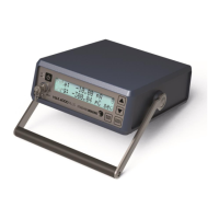
MAX 4000 PLUS ELECTROMETER 17
Operating Parameters:
Temperature:
Relative Humidity:
Pressure:
15 to 35 °C
20 to 80% non-condensing
650 to 770 mmHg
Storage Parameters:
Temperature:
Relative Humidity:
Pressure:
-15 to 50 °C
10 to 95% non-condensing
600 to 800 mmHg
Backlit LCD, 2 x 20 with 5/16 in. high characters
BNC two lug triaxial connector
Bias Voltage:
Five user settings:
Nominal ±450 volt bias
-450, -400, -350, -300, -250, -200, -150, -100, 0, 100, 150, 200,
250, 300, 350, 400, 450 (VDC)
Zero via button push - Display indicates zeroing in progress
RS-232, Default: Uni-directional 19,200 baud, 8 data bits, no
parity, 1 stop bit
Bi-directional operation via:
1: Standard Imaging MAX COMM Software (included)
2: Argus QC4 Software
3: User provided-request Tech Note Doc No. 4426
Dimensions:
Width:
Height:
Length:
22.6 cm (8.91 in)
7.87 cm (3.10 in)
24.8 cm (9.76 in)
6V 1300 mAh, sealed lead-acid
100-240 VAC, 0.5 A max, 50/60 Hz input to external power
supply, 9 VDC, 2. A power supply output to electrometer
input, Globtek
®
, Inc. power supply model GTM96180-1811-2.0-T3
or TRUMPower power supply model FRM015-S09-4
The use of any other power supply and using alternates other
than the UL/CSA recognized power cord can degrade
minimum safety. The proper replacements from Standard
Imaging, Inc. are required for compliance with the
requirements of IEC 60601-1.
IEC 60601-1
1
, IEC 60601-1-2
1
, IEC 60731
2
1
Externally Certified;
2
Designed to Meet
Class I - External Power Supply
Class II - Electrometer / Internally Powered - Electrometer
Unit