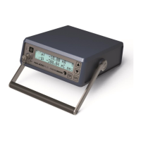
MAX 4000 PLUS ELECTROMETER 6
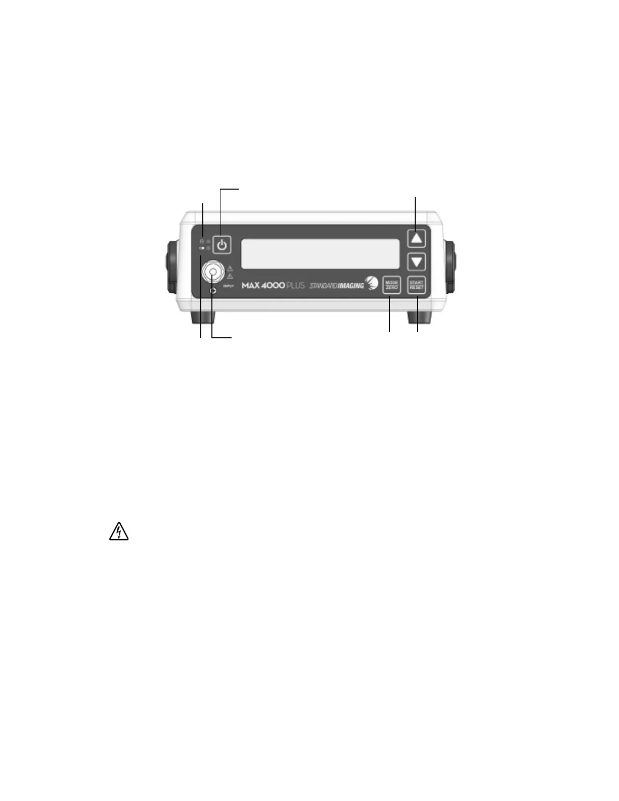
2 Front Panel
1 Power/Standby LED: When lit, the MAX 4000 Plus is powered on.
2 Power button: Turns the unit on/off.
3 Battery Charging LED: When lit, the battery charger is energized and charging the internal
battery.
4 Input connection: A standard two lug, BNC, triax connector for signal input. This connector
features low leakage current properties. The signal current is carried on the central lead, the
guard carries the high voltage and the outermost ring is ground.
0-450 VDC / 350 µA max
To protect the input connector, always replace the chain cap when the MAX 4000 Plus is not
in use.
5 MODE/ZERO button: Press to toggle through the modes in the following order: Range, Bias,
Threshold Levels, Rate, Charge and
Rate/Charge. Press and hold for 2 seconds to select the zero adjustment procedure and
perform system zero.
6 START/RESET button: Press to start and stop timed charge collections in the Charge or
Rate/Charge mode, or to reset the display following a collection.
7 Arrow buttons: Press to toggle the Range selection, voltages in the Bias Mode, or to select
the time period increments for taking a charge reading.