G
B
14
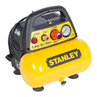
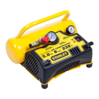
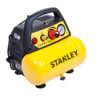
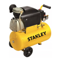
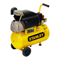
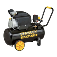
2. FEATURES (Pics. 1-2-3)
A. I/O Switch: The I/O switch is the activation
mechanism that is used to start and stop the
compressor.Whentheswitchis“On”,themotorand
pump will compress air until tank pressure reaches
theupperlimitofthefactorysetoperatingpressure.
Whentankpressurefallsbelowthefactoryset“cut
in”pressure,thecompressorwillagainautomatically
starttocompressair.
B. Tank Pressure Gauge: The tank pressure gauge
indicates the air pressure that is present in the tank
inPSI(andBAR).
C. Regulated Pressure Gauge: The regulated
pressure gauge indicates the amount of pressure
that is allowed into the discharge line according to
thesettingoftheregulator.
D. Regulator Knob: The regulator knob is used
to adjust the air pressure that is available at
thedischargeline.Thedischargeairpressure
is increased by turning the knob clockwise and
decreasedbyturningtheknobcounterclockwise.
E. Drain Valve: Ball style valve that drains moisture
fromthetankwhenopened.
F. Quick Coupler: The quick coupler is used to connect
theairlinetoyourtool.
G. Safety valve:Thesafetyvalveissettoavoidover-
pressurizationoftheairtanks.Thisvalveisfactory
pre-setat10bar(145PSI)andwillnotfunction
unlesstankpressurereachesthispressure.Do not
attempt to adjust or eliminate this safety device.
Any adjustments to this valve could cause
serious injury. If this device requires service or
maintenance,seeanAuthorizedServiceCenter.
H. Handle for lifting/moving.
I. Shoulder belt for easy transport and use: The
compressor may be conveniently carried using the
shoulderbelt.
– If the metal rings have not already been fitted,
insert the two rings in the two holes in the ends of
thealuminiumhandle(asshowninFigure7a).
–
To fit the belt to the compressor: attach the shoulder
strap by inserting the snap hooks into the metal rings
ontheendsofthehandle(asshowninFigure7b).
J. Strip attach/detach: In case the compressor is fitted
withaVelcro®strip,usethisstriptosecureanair-
operatedtool(e.g.:nailer)oraPVCextensionpipe
to the body of the compressor (as shown in Figures
6a-6b).
K. Storage box for accessories.
3. SCOPE OF USE
The compressor is designed for generating compressed
airfortoolsoperatedbycompressedair.
Please note that our equipment has not been designed
for use in commercial, trade or industrial applications.
Our warranty will be voided if the machine is used in
commercial, trade or industrial businesses or for equivalent
purposes.
Themachineistobeusedonlyforitsprescribedpurpose.
Anyotheruseisdeemedtobeacaseofmisuse.Theuser/
operator and not the manufacturer will be liable for any
damageorinjuriesofanykindcausedasaresultofthis.
4. ELECTRICAL GROUNDING
INSTRUCTIONS
Thisproductshouldbeelectricallygrounded.Intheevent
of an electrical short circuit, grounding reduces the risk of
electrical shock by providing an escape wire for electrical
current. This product is equipped with a cord having
a grounding wire with an appropriate grounding plug.
The plug must be plugged into an outlet that is properly
installed and grounded in accordance with all local codes
andordinances.
4.1 Connection of the mains plug
Important!
The wires in the mains lead fitted to this product are
colouredinaccordancewiththecodeshowninpic.9.
● Thisproductisdoubleinsulatedandthereforedoes
not require a connection to earth.
● The3pinplugmustcomplytoBS1363/A.
● FusemustcomplytoBS1362.
If for any reason the 13 amp plug fitted to this product
requires replacement it must be wired in accordance with
the following instruction:
Do not connect the brown (live) or blue (neutral) to the
earth pin marked ‘E’ on the 3 pin plug.
ConnecttheBluewiretotheterminalmarkedNeutral(N).
ConnecttheBrownwiretotheterminalmarkedLive(L).
Ensure that the outer insulation is gripped by the cord grip
and that the wires are not trapped when replacing the plug
cover.Themainsleadonthisproductisfittedwitha13
amp(BS1363/A)plug.A13amp(BS1362)fusemustbe
fittedintheplug.
If in doubt consult a qualified electrician
● When using compressed air, you must know and comply
with the safety precautions to be adopted for each type of
application (inflation, pneumatic tools, painting, washing
withwater-baseddetergentsonly,etc.).
● Never exceed the maximum allowable pressure
recommended by the manufacturer of any attachment or
accessoryyouusewiththiscompressor.
 Loading...