8
ENGLISH
(Original instructions)
● Plug the charger (9) into an appropriate outlet before
inserting battery pack (6).
● The green charging light (9a) will blink continuously
indicating that the charging process has started.
● The completion of charge will be indicated by the green
charging light (9a) remaining ON continuously. The battery
pack (6) is fully charged and may be removed and used at
this time or left in the charger.
● Charge discharged batteries within 1 week. Battery life will
be greatly diminished if stored in a discharged state.
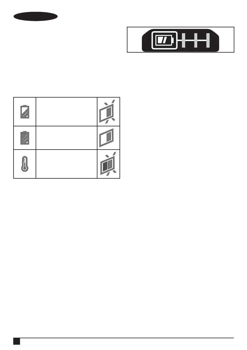
Charger LED Modes
Charging:
Green LED Intermittent
Fully Charged:
Green LED Solid
Hot/Cold Pack Delay:
Green LED Intermittent
Red LED Solid
Note: The compatible charger(s) will not charge a faulty
battery pack. The charger will indicate a faulty battery pack by
refusing to light.
Note: This could also mean a problem with a charger. If the
charger indicates a problem, take the charger and battery
pack to be tested at an authorized service centre.
Leaving the battery in the charger
The charger and battery pack can be left connected with the
LED glowing indenitely. The charger will keep the battery
pack fresh and fully charged.
Hot/Cold Pack Delay
When the charger detects a battery that is too hot or too
cold, it automatically starts a Hot/Cold Pack Delay, the green
LED (9a) will ash intermittently, while the red LED (9b) will
remain on continuously, suspending charging until the battery
has reached an appropriate temperature. The charger then
automatically switches to the pack charging mode. This
feature ensures maximum battery life.
Battery state of charge indicator (Fig. B)
The battery includes a state of charge indicator to quickly
determine the extent of battery life as shown in gure B. By
pressing the state of charge button (6a) you can easily view
the charge remaining in the battery as illustrated in gure B.
Installing and Removing the Battery Pack from
the tool
@
Warning! Make certain the lock-off button is engaged
to prevent switch actuation before removing or
installing battery.
To install battery pack (Fig. C)
● Insert battery pack rmly into tool until an audible click is
heard as shown in gure C. Ensure battery pack is fully
seated and fully latched into position.
To remove battery pack (Fig. D)
● Depress the battery release button (7) as shown in gureD
and pull battery pack out of tool.
Belt hook (Optional extra) (Fig. E, F)
@
Warning! To reduce the risk of serious personal
injury, place the forward/reverse button in the lock-off
position or turn tool off and disconnect battery pack
before making any adjustments or removing/installing
attachments or accessories. An accidental start-up
can cause injury.
@
Warning! To reduce the risk of serious personal
injury, ONLY use the tool’s belt hook (10) to hang the
tool from a work belt. DO NOT use the belt hook for
tethering or securing the tool to a person or object
during use. DO NOT suspend tool overhead or
suspend objects from the belt hook.
@
Warning! To reduce the risk of serious personal
injury, ensure the screw (11) holding the belt hook
is secure.
Note: When attaching or replacing the belt hook (10), use only
the screw (11) that is provided. Be sure to securely tighten
the screw.
The belt hook (10) can be be attached by sliding into the
slots (12) on either side of the tool using only the screw (11)
provided, to accommodate left- or right- handed users. If the
hook is not desired at all, it can be removed from the tool.
To move the belt hook, remove the screw (11) that holds the
belt hook (10) in place then reassemble on the opposite side.
Be sure to securely tighten the screw (11).
Note: Various trackwall hooks and storage congurations
are available.
Please visit our website www.stanleytools.eu/3 for
further information.
Keyless chuck (Fig. G)
@
Warning! Make certain the battery pack is removed
to prevent tool actuation before installing or
removing accessories.
 Loading...