© 2005, THE STANLEY WORKS. ALL RIGHTS RESERVED.
204027
Rev. C, 11/9/05
9 of 31
3.6 Wiring the Operator for Required Handing (Magic-Force Operators)
NOTE
Operator cams are factory-set for right hand operation.
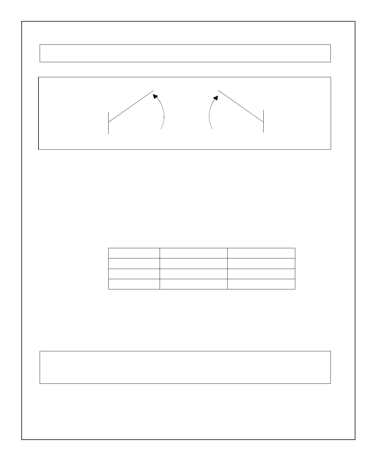
3.6.1 Refer to Figure 4, and DETERMINE door handing.
3.6.2 CONNECT encoder cable adapter 415001 from encoder to control box encoder 1 and
encoder 2 connectors if applicable.
3.6.3 If Sentrex™ is installed with a left hand Magic-Force operator, refer to Attachment 2 or
3 and INSTALL encoder handing harness (part No. 413767).
3.6.4 CONNECT operator harness from close speed module to control box motor 1 and
motor 2 connectors if applicable
3.7 Wiring the “ON/OFF/HOLD OPEN” Switch and Power Switch
3.7.1 Refer to Attachment 5, and CONNECT “ON/OFF/HOLD OPEN” switch wiring as
follows:
TB2 Terminal Connection Switch Wire Color
1 Hold open Yellow
2 Common Orange
3 Automatic Violet
3.7.2 SET “POWER” switch to “OFF.”
3.7.3 CONNECT “POWER” switch harness 516857-1 to power harness 415000.
3.7.4 CONNECT line connect harness 412544 to power harness 415000.
3.8 Wiring the Door Activation or Safety Device
NOTE
Attachments 2, 3, and 4 illustrate typical wiring for various devices. Though the specific device may not be
shown, this attachment can be used as a general guide. Specific wiring instructions from the manufacturer
must also be consulted.
3.8.1 Refer to Attachment 2, 3, or 4 and applicable manufacturer's instructions, and
CONNECT door activation or safety device.
Figure 4. Door Handing
LEFT HAND RIGHT HAND
DOOR
OPENING
MOTION
MCB004