204027
Rev. C, 11/9/05
Page 28 of 31
© 2005, THE STANLEY WORKS. ALL RIGHTS RESERVED.
Attachment 6
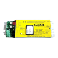
MC521 Controller Controls and Indicators
(Sheet 2 of 2)
ITEM CONTROL/
INDICATOR
DESCRIPTION
1 Motor 2 Connector J109 Motor No. 2 connector.
2 Power Connector J1101 Connection point for incoming line, neutral, and common power wiring.
3 Fuse Z1101 Controller fuse-- 5 Amp, 250V
4 Motor 1 Connector J601 Motor No. 1 connector.
5 Terminal Block Connector
TB1
Connection point for door cycle counter and Sentrex.
6 Terminal Block Connector
TB2
Connection point for function switch (rocker).
7 Encoder 2 Connector J403 Connection point for motor encoder No. 2.
8 Two Digit Display Displays Controller Status. Also serves as the display for tune-in by pushbutton switches.
9 Encoder 1 Connector J402 Connection point for motor encoder No. 1.
10 Up Pushbutton Switch
S302
Used manual setup and tuning of door when PDA is not available.
11 Down Pushbutton Switch
S303
Used for manual setup and tuning of door when PDA is not available.
12 Enter Pushbutton Switch
S301
Used for manual setup and tuning of door when PDA is not available.
13 COMM1 Jack RS232 COMM1 connector. Connection point for PDA harness.
14 COMM2 Jack RS232 COMM2 connector. Future provision.
15 Terminal Block Connector
TB5
Not used.
16 Terminal Block Connector
TB4
Connection point for operate sensor, safety sensor, and push plate.
17 Terminal Block Connector
TB3
Connection point for stall sensor, safety sensor, and breakout switch. Using jumper wires across TB3 terminals 1 to
5 and 2 to 6, internal transformer supplies power to multiple external sensors.
18 J401 Connection point for Sentrex microboard.

 Loading...