EasyManuals Logo

Stanley Omnilock 45HOM User Manual

Stanley Omnilock 45HOM
12 pages
To Next Page IconTo Next Page
To Previous Page IconTo Previous Page
Page #2 background imageLoading...
Page #2 background image
Installation Instructions for Stanley Omnilock 45HOM Mortise Locks
Stanley Omnilock
a Product Group of Stanley Security Solutions, Inc.
2
Planning the installation
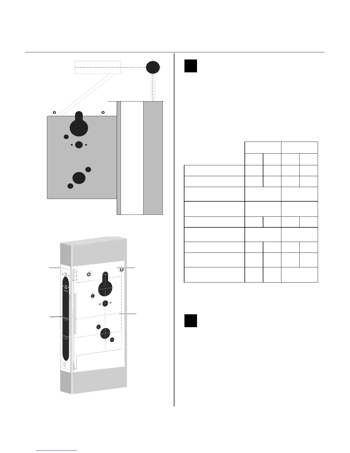
1 Identify holes to drill
1 Determine the lock function to be installed.
2 Determine the inside and outside, hand, and
bevel of the door.
3 See the Holes by Function table and Figure 3 to
determine the holes to be drilled for the lock
function.
2 Position template and mark drill
points
Note: If the door is a fabricated hollow metal door,
determine whether it is properly reinforced to
support the lock. If door reinforcement is not
adequate, consult the door manufacturer for
information on proper reinforcement. For
dimensions for preparing metal doors, see the OM2
Template — Installation Specifications for
45HOM Mortise Locks (T83318).
Functions
Holes by Function
DV TV
Door side In Out In Out
A Cylinder
■■
B Thumb turn
C Lever
a
Through
door
Through
door
D Trim mounting
(2 holes)
a
a. Because these holes pass through the mortise pocket, it is
recommended that each hole be drilled separately rather
than straight through.
Through
door
Through
door
E Grounding hole
F Through bolt hole
Through
door
Through
door
G Standoff hole
■■
H Thumb turn mounting
screw (2 holes)
J Door Status Switch
(Optional)
Door
Edge
G
E
B
C
D
D
F
F
G
H H
A
J
For hole sizes, see
the OM1 Template
T83316
Figure 1 Identifying holes to drill
Horizontal cen
ter
line
of
lock
3/8 in
10 m
m
7/8
in
23
m
m
H
B
1/2 in
13 mm
Horizontal
cen
ter
line
of lever
Alig
n to edge
of door
r.
Note
:
Use
this
tem
pla
te
for
th
e
insid
e
of
aLH
or
LH
RB
door
or
the
o
utside
(k
eyed
side)
of
aRH
or
RHRB
doo
r.
Detach here
Strike lip
Lowedg
e
(na
rrow
sid
e)
Flat edg
e–
no beve
l
Highedg
e
(w
i
de side)
A
E
FF
D
D
5/16 in
8mm
1/8 in
3mm
3/16 in
5mm
3/16 in
5mm
Hole Desc
riptions
ACyinder (1)
BThu
m
bturn(1)
C Lev
er (1)
DTrimm
ounting
(2
)
E
Grou
nding
(1)
F Module
bol
t
(2)
G
Module sta
ndof
f
(2)
H Thumb
turn
m
oun
tin
g
screw
(2)
G
5/16 in
8mm
3/8 in
10 mm
A
G
5/16 in
8mm
C
11/4in
32 m
m
Vertical
center
lin
e
of leve
r
T
o
e
n
s
u
r
e
a
c
c
u
r
a
t
e
d
o
o
r
p
r
e
p
a
r
a
t
i
o
n
,
u
s
e
o
n
l
y
f
a
c
t
o
r
y
-
p
r
i
n
t
e
d
t
e
m
p
l
a
t
e
s
.
D
o
n
o
t
u
s
e
c
o
p
i
e
s
o
r
f
a
c
s
i
m
i
l
i
e
s
.
Figure 2 Aligning the templates
Installation
template
Door edge
template
Centerline
Centerline

Other manuals for Stanley Omnilock 45HOM

Questions and Answers:

Question and Answer IconNeed help?

Do you have a question about the Stanley Omnilock 45HOM and is the answer not in the manual?

Stanley Omnilock 45HOM Specifications

General IconGeneral
BrandStanley
ModelOmnilock 45HOM
CategoryLocks
LanguageEnglish

Related product manuals