EasyManua.ls Logo

Stanley Omnilock 45HOM User Manual

Stanley Omnilock 45HOM
12 pages
To Next Page IconTo Next Page
Page #1 background imageLoading...
Page #1 background image
Stanley Omnilock
a Product Group of Stanley Security Solutions, Inc.
1
Planning the installation
T83312/Rev A 000000 ER-7991-12 Jan 2010
Contents
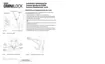
These installation instructions describe how to install
your 45HOM Mortise Lock. Topics covered include:
Planning the installation...........................................1
Preparing the door and door jamb..........................4
Installing the lock........................................................7
Completing the installation......................................9
Site survey
Use the following survey to record information
about the installation site. You need this information
to determine how to prepare the door for the lock.
Door information
Door handing and bevel:
If a handing change is required, see “Rotate latchbolt
(if necessary)” on page 4.
Left hand (LH)
Left hand, reverse bevel (LHRB)
Right hand (RH)
Right hand, reverse bevel (RHRB)
Door thickness: 1-3/4 to 2 inches (44 to 50 mm).
Environment information
a. See Stanley installation instruction Addendum (T83317)
Extreme Weatherized Installation for the extreme weatherized
model installation.
Model
Side of
door
Temperature
Range
Exposure
Standard Outside
+32°F to +129°F
0°C to +54°C
Drip proof.
Inadvertent
splashing of
water spray
acceptable.
Weatherized Outside
-4°F to +129°F
-20°C to +54°C
Direct exposure
to rain and snow
Extreme
Weatherized
a
Outside
-40°F to +129°F
-40°C to + 54°C
Direct exposure
to rain and snow
Inside
+32°F to +129°F
0°C to +54°C
N/A
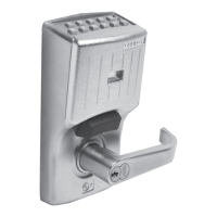
Installation Instructions for
Stanley Omnilock 45HOM
Mortise Locks
Components checklist
Use the following checklist to make sure that you
have the items necessary to install your Omnilock
Mortise Lock.
Components provided in the box:
Inside and outside trim cassettes
Inside and outside rose and rose ring
Outside escutcheon assembly
Mortise case assembly
Mortise cylinder and collar
Outside lever and spindle assembly
Inside lever
Strike package
Installation template and instructions
Screw package
Mortise case faceplate
Batteries
Torx T15 driver
1/8” hex wrench
Other components:
Programming Default ID Card (provided with
software)

Other manuals for Stanley Omnilock 45HOM

Questions and Answers:

Stanley Omnilock 45HOM Specifications

General IconGeneral
BrandStanley
ModelOmnilock 45HOM
CategoryLocks
LanguageEnglish

Summary

Planning the Installation

Site Survey

Use the following survey to record information about the installation site.

Door Information

Details regarding door handing, bevel, and thickness for lock preparation.

Environment Information

Specifies temperature ranges and exposure conditions for different lock models.

Components Checklist

Components Provided in the Box

Lists all parts included within the Omnilock Mortise Lock packaging.

Other Components

Lists additional items required or provided alongside the lock system.

Holes to Drill and Template Positioning

Identify Holes to Drill

Determine lock function, door hand/bevel, and required holes using the function table.

Position Template and Mark Drill Points

Align templates on the door and mark positions for drilling holes.

Center Punching and Drilling

Center Punch and Drill Holes

Center punch drill points and then drill the necessary holes as per template instructions.

Install Door Status Switch

Optional step for wireless TV models to install the door status switch.

Mortise Case Configuration and Installation

Configuring & Installing the Mortise

Install door status switch, rotate latchbolt, and position hub toggles if necessary.

Rotate Latchbolt

Rotate the latchbolt 180 degrees to match the door handing if required.

Position Hub Toggles

Check and adjust hub toggle positions for desired lock operation.

Installing the Trim

Install Mortise Case

Insert the mortise case into the mortise cavity, feeding wires and securing it.

Install Trim Mounting Plates

Insert the outside trim mounting plate through the door and mortise case.

Installing the Lock

Install Inside Trim Mounting Plate

Position and secure the inside trim mounting plate opposite the outside plate.

Install Thumb Turn

Orient and install the thumb turn for TV function models.

Install Inside and Outside Levers

Insert and secure the inside and outside levers onto the spindles.

Battery Installation

Install Batteries

Install batteries, connect wires, and reset electronics for operation verification.

Connecting Escutcheon Wires

Install Outside Escutcheon

Attach the outside escutcheon to the door, ensuring wires are not pinched.

Connecting Escutcheon Wires

Connect mortise case wires to the escutcheon wiring harness.

Finishing the Installation

Install Cylinder

Thread and secure the cylinder into the mortise case.

Install Mortise Case Faceplate

Secure the mortise case faceplate to the mortise case.

Install Strike Box and Strike Plate

Mortise jamb, drill holes, and install the strike box and strike plate.

Install Core

Insert and rotate the control key to install the core into the cylinder.

Operation and Troubleshooting

Check Operation

Verify proper function of door latches, deadbolt, and key access.

Test Lock

Test the lock for proper operation before programming.

Troubleshooting

Diagnose and resolve issues if the mechanism does not unlock.

Related product manuals