ENGLISH
11
3. TOOL SET UP
IMPORTANT - READ THE SAFETY WARNINGS ON PAGES 4 & 5 CAREFULLY BEFORE PUTTING INTO SERVICE.
IMPORTANT - THE AIR SUPPLY MUST BE TURNED OFF OR DISCONNECTED BEFORE FITTING OR REMOVING
THE NOSE ASSEMBLY.
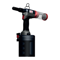
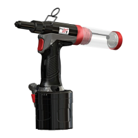
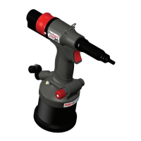
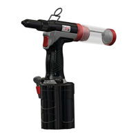
3.1 NOSE EQUIPMENT (REF. FIG. 2)
Item numbers in bold refer to the components in gures 1 & 2 and the tables on page 8.
The XT1 tool will be supplied pre-assembled with the nose piece for 3.2 mm [1/8“] rivets and nose pieces for
2.4 [3/32“] and 4.0mm [5/32] rivets are supplied separately.
The XT2 tool will be supplied pre-assembled with nose piece for 4.8 mm [3/16“] rivets and nose pieces for 3.2
[1/8“] and 4.0 [5/32“] rivets are supplied separately.
Mounting the nose piece
• The air supply must be disconnected.
• Select the correct nose piece for the rivet to be installed.
• Remove the nose housing nut (1p) and nose housing (1d), including nose piece (1a, b or c), and o-ring
(1e) from the tool.
• Remove the nose piece (1a,b,or c) from the nose casing (1d)
• Select the relevant size nose piece and assemble in reverse order.
Removing complete nose equipment.
• The air supply must be disconnected.
• Remove the nose housing nut (1p) and nose housing (1d), including nose piece (1a, b or c), and o-ring
(1e) from the tool.
• Pull back the jaw guide lock (1m) against the spring (1n) and then remove the jaw guide (1f).
• Remove the jaws (1g) from the jaw guide (1f).
• Remove jaw pusher (1h), urethane washer (1i), and Jaw pusher spring (1j), from the pulling head (1l).
Mounting the complete nose equipment
• The air supply must be disconnected
• Any worn or damaged part should be replaced.
• Clean and check wear on jaws (1g).
• Ensure that the jaw pusher (1h) or the jaw pusher spring (1j) are not distorted.
• Lightly coat jaws (1g) with moly lithium grease.
• Drop Jaws (1g) into the jaw guide (1f).
• Insert jaw pusher (1h) and urethane washer (1i) into the pulling head (1l).
• Pull back the jaw guide lock (1m
) and screw the jaw guide (1f) fully on to the pulling head (1l).
• Release the jaw guide lock (1m) and then partially unscrew the jaw guide (1f) until the jaw guide lock (1m)
tooth clicks into the next slot on the jaw guide (1f).
• Place nose casing (1d) over the jaw guide (1f) and tighten fully onto the tool.
Nose assemblies should be serviced at weekly intervals. You should hold some stock of all internal
components of the nose assembly and nose tips as they will need regular replacement.
3.2 AIR SUPPLY (Ref. g. 3.)
Components
A. Stop cock (used during maintenance of lter/regular or lubricated units)
B. Pressure regulator and lter (daily drain)
C. Main supply drain point
D. Take o point from main supply
• All tools are operated with compressed air at a minimum pressure of 5.0 bar.
• Pressure regulators and automatic oiling/ ltering systems to be used on the main air supply within
3metres of the tool (see g. 3).