ENGLISH
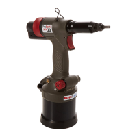
(Ref. fig. 1)
•
Switch OFF air supply at ON/OFF Valve
(7.)
•
Remove all nose equipment (1.) Refer to section 3.1.
•
Remove Bleed Screw (4)and Seal
(5.)
•
Invert tool over suitable container, switch ON air supply at ON/OFF Valve Assembly
(7
)and actuate tool.
•
Residual oil in the tools hydraulic system will empty through bleed screw orifice.
For complete tool servicing we advise that you proceed with dismantling of sub-assemblies in the order
shown below.
Refer to fig. 7 & 8.
6.1 DISMANTLING THE TOOL
6.1.1 Nose Equipment
•
Unscrew the Nose Casing (1e), including the Nose Piece
(la),
and 0 Ring (1f).
•
Pull back the Jaw Guide Lock (1m) against the Spring (1n) and then unscrew the Jaw Guide (1g).
•
Remove the Jaws (1h) from the Jaw Guide (1g).
•
At this point the Jaws (1h) can be cleaned and a light coating of Moly Lithium grease applied or replaced
if worn.
•
Remove Jaw Pusher (11), 0 Ring (1j), and Spring (1k), from the Pulling Head (11).
•
Using spanners, loosen Locknut
(8
)and unscrew the Pulling Head Adapter (1o), Pulling Head (11), Jaw
Guide Lock (1m) and Spring (1n) from the tool piston.
•
Removal of the Pulling Head (11), Jaw Guide Lock (1m) and Spring (1n) from the Pulling Head Adapter (1o)
should not be necessary.
Reassemble as follows:
•
Any worn or damaged part should be replaced.
•
Clean and check wear on Jaws.
•
Ensure that the Jaw Pusher (11) or the Spring (1k) are not distorted.
•
Assemble in reverse order to the removal instructions above.
•
Lightly coat Jaws (1h) with Moly Lithium grease.
•
Drop Jaws (1h) into the Jaw Guide (1g).
•
Insert Jaw Pusher (11) and 0 Ring (1j) into the Pulling Head (11).
•
Pull back the Jaw Guide Lock (1m) and screw the Jaw Guide (1g) fully on to the Pulling Head (11). Release
the Jaw Guide Lock (1m) and then partially unscrew the Jaw Guide (1g) until the Jaw Guide Lock (1m) tooth
clicks into the next slot on the Jaw Guide (1g).
•
Place Nose Casing (1e) over the Jaw Guide (1g) and screw fully onto the tool.
6.1.2 Head Assembly
•
Rotated the Stem Collector
(3
)anti-clockwise and remove from the Collector Adapter
(27).
Refer to fig. 3.
•
Unscrew the Deflector Retaining Nut
(29)
together with the Deflector
(28).
•
Pull off the Collector Adapter
(27)
and 0 ring
(59).
•
Unscrew the End Cap Assembly
(25)
together with 0 ring
(26)
and 0 ring
(58).
Care should be taken as the
End Cap Assembly will be under load from the Spring
(22).
•
Remove Spring
(22).
•
Unscrew and remove Locknut
8
from the Piston Assembly
(19).
•
Push the Piston Assembly
(19),
together with the Ejector Nozzle
(23)
and 0 rings
(24),
to the rear and out
of the Head Assembly
(12)
taking care not to damage the cylinder bore or piston shaft.
•
Using circlip pliers (07900-00164) remove the seal retainer
(17)
then push the Rod Seal
(16)
and Bearing
Tape
(15)
to the rear and out of the Head Assembly
(12).
•
Remove the Seal Housing (10) and Lip Seal (11).
POP a
Avdel°
18
(Ref. g. 1)
• Switch OFF air supply at ON/OFF Valve (7.)
• Remove all nose equipment (1.) Refer to section 3.1.
• Remove Bleed Screw (4)and Seal (5.)
• Invert tool over suitable container, switch ON air supply at ON/OFF Valve Assembly (7 )and actuate tool.
• Residual oil in the tools hydraulic system will empty through bleed screw orice.
For complete tool servicing we advise that you proceed with dismantling of sub-assemblies in the order
shown below.
Refer to g. 7 & 8.
6.1 DISMANTLING THE TOOL
6.1.1 Nose Equipment
• Unscrew the Nose Casing (1e), including the Nose Piece (1a), and O Ring (1f).
• Pull back the Jaw Guide Lock (1m) against the Spring (1n) and then unscrew the Jaw Guide (1g).
• Remove the Jaws (1h) from the Jaw Guide (1g).
• At this point the Jaws (1h) can be cleaned and a light coating of Moly Lithium grease applied or replaced
if worn.
• Remove Jaw Pusher (1i), O Ring (1j), and Spring (1k), from the Pulling Head (1l).
• Using spanners, loosen Locknut (8 )and unscrew the Pulling Head Adapter (1o), Pulling Head (1l), Jaw
Guide Lock (1m) and Spring (1n) from the tool piston.
• Removal of the Pulling Head (1l), Jaw Guide Lock (1m) and Spring (1n) from the Pulling Head Adapter (1o)
should not be necessary.
Reassemble as follows:
• Any worn or damaged part should be replaced.
• Clean and check wear on Jaws.
• Ensure that the Jaw Pusher (1i) or the Spring (1k) are not distorted.
• Assemble in reverse order to the removal instructions above.
• Lightly coat Jaws (1h) with Moly Lithium grease.
• Drop Jaws (1h) into the Jaw Guide (1g).
• Insert Jaw Pusher (1i) and O Ring (1j) into the Pulling Head (1l).
• Pull back the Jaw Guide Lock (1m) and screw the Jaw Guide (1g) fully on to the Pulling Head (1l). Release
the Jaw Guide Lock (1m) and then partially unscrew the Jaw Guide (1g) until the Jaw Guide Lock (1m) tooth
clicks into the next slot on the Jaw Guide (1g).
• Place Nose Casing (1e) over the Jaw Guide (1g) and screw fully onto the tool.
6.1.2 Head Assembly
• Rotated the Stem Collector (3 )anti-clockwise and remove from the Collector Adapter (27). Refer to g. 3.
• Unscrew the Deector Retaining Nut (29) together with the Deector (28).
• Pull o the Collector Adapter (27) and O ring (59).
• Unscrew the End Cap Assembly (25) together with O ring (26) and O ring (58). Care should be taken as the
End Cap Assembly will be under load from the Spring (22).
• Remove Spring (22).
• Unscrew and remove Locknut 8 from the Piston Assembly (19).
• Push the Piston Assembly (19), together with the Ejector Nozzle (23) and O rings (24), to the rear and out
of the Head Assembly (12) taking care not to damage the cylinder bore or piston shaft.
• Using circlip pliers (07900-00164) remove the seal retainer (17) then push the Rod Seal (16) and Bearing
Tape (15) to the rear and out of the Head Assembly (12).
• Remove the Seal Housing (10) and Lip Seal (11).
ENGLISH
18