8
ENGLISH
uprights. Note that Part 2 should be positioned as shown in
Fig. B4. Connect Part 4 (top cross support) to the top of the
frame. Note that Part 4 should be positioned as shown in
Fig. B4.
Step 4
Now place and connect the ends of the top and center frame
supports to the frame. Take care to ensure that the supports
are positioned as shown in Fig. B5.
Step 5
Once you are satisfied that the frame is assembled correctly,
fully tighten ALL the bolts. Finally, assemble the 4 foot pads to
the bottom of each leg (see Fig. B6).
2. Assemble the stand’s legs
Step 1
Select the following parts:
2 x Part 1
1 x Part 3
1 x Part 5
Lay the parts together as shown in Fig. B1, B2, and B3. This
is best done by simply laying the parts loosely together on the
floor. Once you are satisfied that you have the parts correctly
laid together, start the fitting process.
Align the holes and secure with the bolts as shown in
Fig. B1.
DO NOT fully tighten the bolts, nuts and washers at this point.
Finger tight is sufficient.
Step 2
Repeat Step 1 so that there are two frames assembled.
Step 3
Select the following parts:
2 x Part 2
2 x Part 4
These will form the crosspieces between the previously
assembled frames. Lay the parts flat on the floor. Connect the
longer Part (2) and fix it to the frame in the center of the
B1
B2
B3
B1
5
3
2
4
B4
1
B6
5
1
4
B5
Langkah 4
Sekarang tempatkan dan sambungkan bagian ujung atas dan
tengah penyangga kerangka ke kerangka. Berhati-hatilah
untuk memastikan bahwa penyangga diposisikan seperti yang
ditunjukkan dalam Gbr. B5.
8
ENGLISH
uprights. Note that Part 2 should be positioned as shown in
Fig. B4. Connect Part 4 (top cross support) to the top of the
frame. Note that Part 4 should be positioned as shown in
Fig. B4.
Step 4
Now place and connect the ends of the top and center frame
supports to the frame. Take care to ensure that the supports
are positioned as shown in Fig. B5.
Step 5
Once you are satisfied that the frame is assembled correctly,
fully tighten ALL the bolts. Finally, assemble the 4 foot pads to
the bottom of each leg (see Fig. B6).
2. Assemble the stand’s legs
Step 1
Select the following parts:
2 x Part 1
1 x Part 3
1 x Part 5
Lay the parts together as shown in Fig. B1, B2, and B3. This
is best done by simply laying the parts loosely together on the
floor. Once you are satisfied that you have the parts correctly
laid together, start the fitting process.
Align the holes and secure with the bolts as shown in
Fig. B1.
DO NOT fully tighten the bolts, nuts and washers at this point.
Finger tight is sufficient.
Step 2
Repeat Step 1 so that there are two frames assembled.
Step 3
Select the following parts:
2 x Part 2
2 x Part 4
These will form the crosspieces between the previously
assembled frames. Lay the parts flat on the floor. Connect the
longer Part (2) and fix it to the frame in the center of the
B1
B2
B3
B1
5
3
2
4
B4
1
B6
5
1
4
B5
Langkah 5
Setelah Anda senang bahwa kerangka dirakit dengan benar,
kencangkan erat-erat SEMUA baut. Terakhir, rakitlah bantalan
4 kaki ke bagian bawah dari masing-masing kaki (lihat
Gbr. B6).
8
ENGLISH
uprights. Note that Part 2 should be positioned as shown in
Fig. B4. Connect Part 4 (top cross support) to the top of the
frame. Note that Part 4 should be positioned as shown in
Fig. B4.
Step 4
Now place and connect the ends of the top and center frame
supports to the frame. Take care to ensure that the supports
are positioned as shown in Fig. B5.
Step 5
Once you are satisfied that the frame is assembled correctly,
fully tighten ALL the bolts. Finally, assemble the 4 foot pads to
the bottom of each leg (see Fig. B6).
2. Assemble the stand’s legs
Step 1
Select the following parts:
2 x Part 1
1 x Part 3
1 x Part 5
Lay the parts together as shown in Fig. B1, B2, and B3. This
is best done by simply laying the parts loosely together on the
floor. Once you are satisfied that you have the parts correctly
laid together, start the fitting process.
Align the holes and secure with the bolts as shown in
Fig. B1.
DO NOT fully tighten the bolts, nuts and washers at this point.
Finger tight is sufficient.
Step 2
Repeat Step 1 so that there are two frames assembled.
Step 3
Select the following parts:
2 x Part 2
2 x Part 4
These will form the crosspieces between the previously
assembled frames. Lay the parts flat on the floor. Connect the
longer Part (2) and fix it to the frame in the center of the
B1
B2
B3
B1
5
3
2
4
B4
1
B6
5
1
4
B5
Luruskan lubang dan kencangkan dengan baut seperti yang
ditunjukkan di
Gbr. B1.
JANGAN kencangkan baut, mur, dan ring sepenuhnya pada
tahap ini. Cukup kencangkan dengan jari.
Langkah 2
Ulangi Langkah 1, sehingga hanya ada dua kerangka yang
dirakit.
8
ENGLISH
uprights. Note that Part 2 should be positioned as shown in
Fig. B4. Connect Part 4 (top cross support) to the top of the
frame. Note that Part 4 should be positioned as shown in
Fig. B4.
Step 4
Now place and connect the ends of the top and center frame
supports to the frame. Take care to ensure that the supports
are positioned as shown in Fig. B5.
Step 5
Once you are satisfied that the frame is assembled correctly,
fully tighten ALL the bolts. Finally, assemble the 4 foot pads to
the bottom of each leg (see Fig. B6).
2. Assemble the stand’s legs
Step 1
Select the following parts:
2 x Part 1
1 x Part 3
1 x Part 5
Lay the parts together as shown in Fig. B1, B2, and B3. This
is best done by simply laying the parts loosely together on the
floor. Once you are satisfied that you have the parts correctly
laid together, start the fitting process.
Align the holes and secure with the bolts as shown in
Fig. B1.
DO NOT fully tighten the bolts, nuts and washers at this point.
Finger tight is sufficient.
Step 2
Repeat Step 1 so that there are two frames assembled.
Step 3
Select the following parts:
2 x Part 2
2 x Part 4
These will form the crosspieces between the previously
assembled frames. Lay the parts flat on the floor. Connect the
longer Part (2) and fix it to the frame in the center of the
B1
B2
B3
B1
5
3
2
4
B4
1
B6
5
1
4
B5
Langkah 3
Pilih bagian berikut:
2 x Bagian 2
2 x Bagian 4
Bagian ini akan membentuk bagian silang antara kerangka
yang dirakit sebelumnya. Letakkan bagian di lantai yang datar.
Sambungkan Bagian (2) yang lebih panjang dan kencangkan
pada kerangka di bagian tengah penyangga. Perhatikan
bahwa Bagian 2 harus diposisikan seperti yang ditunjukkan
dalam Gbr. B4. Sambungkan Bagian 4 (penyangga silang
bagian atas) ke bagian atas kerangka. Perhatikan bahwa
Bagian 4 harus diposisikan seperti yang ditunjukkan dalam
Gbr. B4.
9
BAHASA INDONESIA
Memasang gergaji meja pada penyangga
(lihat GBR. C1, C2)
Ada empat lubang pemasangan pada dudukan gergaji.
4 lubang pemasangan yang sesuai berada di bagian atas
penyangga. Letakkan gergaji meja pada penyangga,
sesuaikan lubang pada dudukan gergaji dengan lubang pada
penyangga, dan kencangkan dengan 4 baut (12) yang
disediakan. KENCANGKAN sepenuhnya.
uprights. Note that Part 2 should be positioned as shown in
Fig. B4. Connect Part 4 (top cross support) to the top of the
frame. Note that Part 4 should be positioned as shown in
Fig. B4.
Step 4
Now place and connect the ends of the top and center frame
supports to the frame. Take care to ensure that the supports
are positioned as shown in Fig. B5.
Step 5
Once you are satisfied that the frame is assembled correctly,
fully tighten ALL the bolts. Finally, assemble the 4 foot pads to
the bottom of each leg (see Fig. B6).
2. Assemble the stand’s legs
Step 1
Select the following parts:
2 x Part 1
1 x Part 3
1 x Part 5
Lay the parts together as shown in Fig. B1, B2, and B3. This
is best done by simply laying the parts loosely together on the
floor. Once you are satisfied that you have the parts correctly
laid together, start the fitting process.
Align the holes and secure with the bolts as shown in
Fig. B1.
DO NOT fully tighten the bolts, nuts and washers at this point.
Finger tight is sufficient.
Step 2
Repeat Step 1 so that there are two frames assembled.
Step 3
Select the following parts:
2 x Part 2
2 x Part 4
These will form the crosspieces between the previously
assembled frames. Lay the parts flat on the floor. Connect the
longer Part (2) and fix it to the frame in the center of the
B1
B2
B3
B1
5
3
2
4
B4
1
B6
5
1
4
B5
Handle assembly (Fig D)
Place washer (e), housing (b), washer (c) and hex nut (d) on
the bolt (a) to assemble the handle (11)
Riving knife set-up (Fig E, F, G)
WARNING! Disconnect the mains cable! The
setup of the riving knife (3) must be checked
before each use.
1. Set the saw blade (4) to the max. cutting depth, put it at 00
position and lock it
2. Remove the table insert (20) (Fig. E)
WARNING! For transport reasons, the riving
knife (3) was fixed in the lower position before
initial commissioning. Only work with the
machine if the riving knife (3) is in the upper
position. Fitting the riving knife (3) in the upper
position is as follows:
3. Loosen the locking handle (f) and push the riving knife (3)
in the upper position (Fig.F)
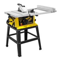
Fitting the table saw to the stand (see FIG. C1, C2)
There are four mounting holes on the base of the saw. 4
corresponding mounting holes are located on the top plane of
the stand. Put the table saw on the stand, match the holes on
the base of the saw with the holes on the stand, and secure
them with the 4 bolts (12) provided. DO fully fasten
Transportation (Fig C3)
Pull out the right side extension as the temporary handle to
transport the table saw on its wheels."
12
C1
12
C2
Pengangkutan (Gbr C3)
Tarik ekstensi sisi kanan sebagai pegangan sementara untuk
mengangkut gergaji meja pada rodanya.”
uprights. Note that Part 2 should be positioned as shown in
Fig. B4. Connect Part 4 (top cross support) to the top of the
frame. Note that Part 4 should be positioned as shown in
Fig. B4.
Step 4
Now place and connect the ends of the top and center frame
supports to the frame. Take care to ensure that the supports
are positioned as shown in Fig. B5.
Step 5
Once you are satisfied that the frame is assembled correctly,
fully tighten ALL the bolts. Finally, assemble the 4 foot pads to
the bottom of each leg (see Fig. B6).
2. Assemble the stand’s legs
Step 1
Select the following parts:
2 x Part 1
1 x Part 3
1 x Part 5
Lay the parts together as shown in Fig. B1, B2, and B3. This
is best done by simply laying the parts loosely together on the
floor. Once you are satisfied that you have the parts correctly
laid together, start the fitting process.
Align the holes and secure with the bolts as shown in
Fig. B1.
DO NOT fully tighten the bolts, nuts and washers at this point.
Finger tight is sufficient.
Step 2
Repeat Step 1 so that there are two frames assembled.
Step 3
Select the following parts:
2 x Part 2
2 x Part 4
These will form the crosspieces between the previously
assembled frames. Lay the parts flat on the floor. Connect the
longer Part (2) and fix it to the frame in the center of the
B1
B2
B3
B1
5
3
2
4
B4
1
B6
5
1
4
B5
Handle assembly (Fig D)
Place washer (e), housing (b), washer (c) and hex nut (d) on
the bolt (a) to assemble the handle (11)
Riving knife set-up (Fig E, F, G)
WARNING! Disconnect the mains cable! The
setup of the riving knife (3) must be checked
before each use.
1. Set the saw blade (4) to the max. cutting depth, put it at 00
position and lock it
2. Remove the table insert (20) (Fig. E)
WARNING! For transport reasons, the riving
knife (3) was fixed in the lower position before
initial commissioning. Only work with the
machine if the riving knife (3) is in the upper
position. Fitting the riving knife (3) in the upper
position is as follows:
3. Loosen the locking handle (f) and push the riving knife (3)
in the upper position (Fig.F)
Fitting the table saw to the stand (see FIG. C1, C2)
There are four mounting holes on the base of the saw. 4
corresponding mounting holes are located on the top plane of
the stand. Put the table saw on the stand, match the holes on
the base of the saw with the holes on the stand, and secure
them with the 4 bolts (12) provided. DO fully fasten
Transportation (Fig C3)
Pull out the right side extension as the temporary handle to
transport the table saw on its wheels."
12
C1
12
C2
C3
Tempatkan ring (e), wadah (b), ring (c) dan mur segi enam (d)
pada baut (a) untuk merakit gagang (11)
uprights. Note that Part 2 should be positioned as shown in
Fig. B4. Connect Part 4 (top cross support) to the top of the
frame. Note that Part 4 should be positioned as shown in
Fig. B4.
Step 4
Now place and connect the ends of the top and center frame
supports to the frame. Take care to ensure that the supports
are positioned as shown in Fig. B5.
Step 5
Once you are satisfied that the frame is assembled correctly,
fully tighten ALL the bolts. Finally, assemble the 4 foot pads to
the bottom of each leg (see Fig. B6).
2. Assemble the stand’s legs
Step 1
Select the following parts:
2 x Part 1
1 x Part 3
1 x Part 5
Lay the parts together as shown in Fig. B1, B2, and B3. This
is best done by simply laying the parts loosely together on the
floor. Once you are satisfied that you have the parts correctly
laid together, start the fitting process.
Align the holes and secure with the bolts as shown in
Fig. B1.
DO NOT fully tighten the bolts, nuts and washers at this point.
Finger tight is sufficient.
Step 2
Repeat Step 1 so that there are two frames assembled.
Step 3
Select the following parts:
2 x Part 2
2 x Part 4
These will form the crosspieces between the previously
assembled frames. Lay the parts flat on the floor. Connect the
longer Part (2) and fix it to the frame in the center of the
B1
B2
B3
B1
5
3
2
4
B4
1
B6
5
1
4
B5
Handle assembly (Fig D)
Place washer (e), housing (b), washer (c) and hex nut (d) on
the bolt (a) to assemble the handle (11)
Riving knife set-up (Fig E, F, G)
WARNING! Disconnect the mains cable! The
setup of the riving knife (3) must be checked
before each use.
1. Set the saw blade (4) to the max. cutting depth, put it at 00
position and lock it
2. Remove the table insert (20) (Fig. E)
WARNING! For transport reasons, the riving
knife (3) was fixed in the lower position before
initial commissioning. Only work with the
machine if the riving knife (3) is in the upper
position. Fitting the riving knife (3) in the upper
position is as follows:
3. Loosen the locking handle (f) and push the riving knife (3)
in the upper position (Fig.F)
Fitting the table saw to the stand (see FIG. C1, C2)
There are four mounting holes on the base of the saw. 4
corresponding mounting holes are located on the top plane of
the stand. Put the table saw on the stand, match the holes on
the base of the saw with the holes on the stand, and secure
them with the 4 bolts (12) provided. DO fully fasten
Transportation (Fig C3)
Pull out the right side extension as the temporary handle to
transport the table saw on its wheels."
12
C1
12
C2
C3
d
c
e
a
11
D
b
Penyesuaian pisau pembelah (Gbr E, F, G)
PERINGATAN! Lepas kabel daya! Penyesuaian
pisau pembelah (3) harus diperiksa sebelum
digunakan.
1. Atur bilah gergaji (4) ke kedalaman pemotongan
maksimal, masukkan di posisi 00 dan kunci
2. Ambil sisipan meja (20) (Gbr. E)
uprights. Note that Part 2 should be positioned as shown in
Fig. B4. Connect Part 4 (top cross support) to the top of the
frame. Note that Part 4 should be positioned as shown in
Fig. B4.
Step 4
Now place and connect the ends of the top and center frame
supports to the frame. Take care to ensure that the supports
are positioned as shown in Fig. B5.
Step 5
Once you are satisfied that the frame is assembled correctly,
fully tighten ALL the bolts. Finally, assemble the 4 foot pads to
the bottom of each leg (see Fig. B6).
2. Assemble the stand’s legs
Step 1
Select the following parts:
2 x Part 1
1 x Part 3
1 x Part 5
Lay the parts together as shown in Fig. B1, B2, and B3. This
is best done by simply laying the parts loosely together on the
floor. Once you are satisfied that you have the parts correctly
laid together, start the fitting process.
Align the holes and secure with the bolts as shown in
Fig. B1.
DO NOT fully tighten the bolts, nuts and washers at this point.
Finger tight is sufficient.
Step 2
Repeat Step 1 so that there are two frames assembled.
Step 3
Select the following parts:
2 x Part 2
2 x Part 4
These will form the crosspieces between the previously
assembled frames. Lay the parts flat on the floor. Connect the
longer Part (2) and fix it to the frame in the center of the
B1
B2
B3
B1
5
3
2
4
B4
1
B6
5
1
4
B5
Handle assembly (Fig D)
Place washer (e), housing (b), washer (c) and hex nut (d) on
the bolt (a) to assemble the handle (11)
Riving knife set-up (Fig E, F, G)
WARNING! Disconnect the mains cable! The
setup of the riving knife (3) must be checked
before each use.
1. Set the saw blade (4) to the max. cutting depth, put it at 00
position and lock it
2. Remove the table insert (20) (Fig. E)
WARNING! For transport reasons, the riving
knife (3) was fixed in the lower position before
initial commissioning. Only work with the
machine if the riving knife (3) is in the upper
position. Fitting the riving knife (3) in the upper
position is as follows:
3. Loosen the locking handle (f) and push the riving knife (3)
in the upper position (Fig.F)
Fitting the table saw to the stand (see FIG. C1, C2)
There are four mounting holes on the base of the saw. 4
corresponding mounting holes are located on the top plane of
the stand. Put the table saw on the stand, match the holes on
the base of the saw with the holes on the stand, and secure
them with the 4 bolts (12) provided. DO fully fasten
Transportation (Fig C3)
Pull out the right side extension as the temporary handle to
transport the table saw on its wheels."
12
C1
12
C2
C3
d
c
e
a
11
D
b
204
E
PERINGATAN! Untuk alasan pengangkutan,
pisau pembelah (3) dipasang pada posisi yang
lebih rendah sebelum uji kelaikan operasi awal.
Hanya gunakan mesin dengan pisau pembelah
(3) berada di posisi atas. Memasang pisau
pembelah (3) di posisi atas adalah sebagai
berikut:
35
BAHASA INDONESIA
 Loading...