8. Place the oven damper in position (Part No.
18) on top of the oven and place the simmering
plate (Part No. 4) in position above it. Place
the oblong hotplate (Part No. 7) and the two
round cleaning cups (Part No.5) in position to
complete the cooker top.
9. Place the bonnet (Part No. 2) in position and fit
its front cleaning door (Part no. 3) in position.
10. Screw the towel rail brackets (Part Nos. 84 and
85) to the top front of the range (Part No. 87)
and fix the towel-rail (Part No.86) in position
between the brackets. Tighten up the screws.
11. Hang the fire door (Part No. 75) and the ashpit
door (Part No. 80) on their hinges.
12. Place the oven shelves in position (Part No.25)
the cast iron shelf below the sheet steel shelf.
13. Place the base cleaning door (Part No. 82) in
position beneath the oven door (Part No. 70).
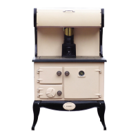
14. Screw the optional splashback (Part No.91)
to its two supports (Part Nos. 88 & 89) keeping
the folded end to the bottom. Screw the plate-
rack (Part No. 90) to the splashback. Screw the
complete assembly on to the cooker hob (Part
No. 9). (See Fig.8)
Note: The Platerack and splashback are an option-
al extra, not supplied as standard.
TOP FLUE EXIT
With the bonnet (Part No 2) in position on the hob,
connect the bonnet ring (Part No 1) onto the top of
the bonnet. The flue pipe is then connected to the
bonnet ring as shown in Fig.6. Seal all joints using
approved fire cement, ensuring that no cement
blocks the flue passageway.
5
Fig.6
FLUES
Flues should be vertical wherever possible and
where a bend is necessary it should not make an
angle of more than 37.5
o
with the vertical.
Horizontal flue runs should be avoided except in the
case of a back outlet appliance, when the length of
the horizontal section should not exceed 300mm.
FLUE PIPES
A flue pipe should only be used to connect an appli-
ance to a chimney and should not pass through any
roof space.
Flue pipes may be of any of the following materials:
(a) Cast iron as described in BS 41:1973 (1981)
(b) Mild steel with a wall thickness of at least
3mm.
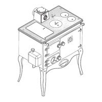
REAR FLUE EXIT
Replace the bonnet (Part No 2) with the hob sealing
plate (Part No 6), using approved fire cement to seal
the hob sealing plate to the hob. Remove the back
Fig.7
Fig.8
sealing plate (Part No 33) and fit the rear outlet spig-
ot (Part No 94) to the flue back (Part No 32).
Connect the flue pipe to the rear flue spigot (see Fig
7). Seal all joints with fire cement ensuring that no
cement blocks the flue passageways.