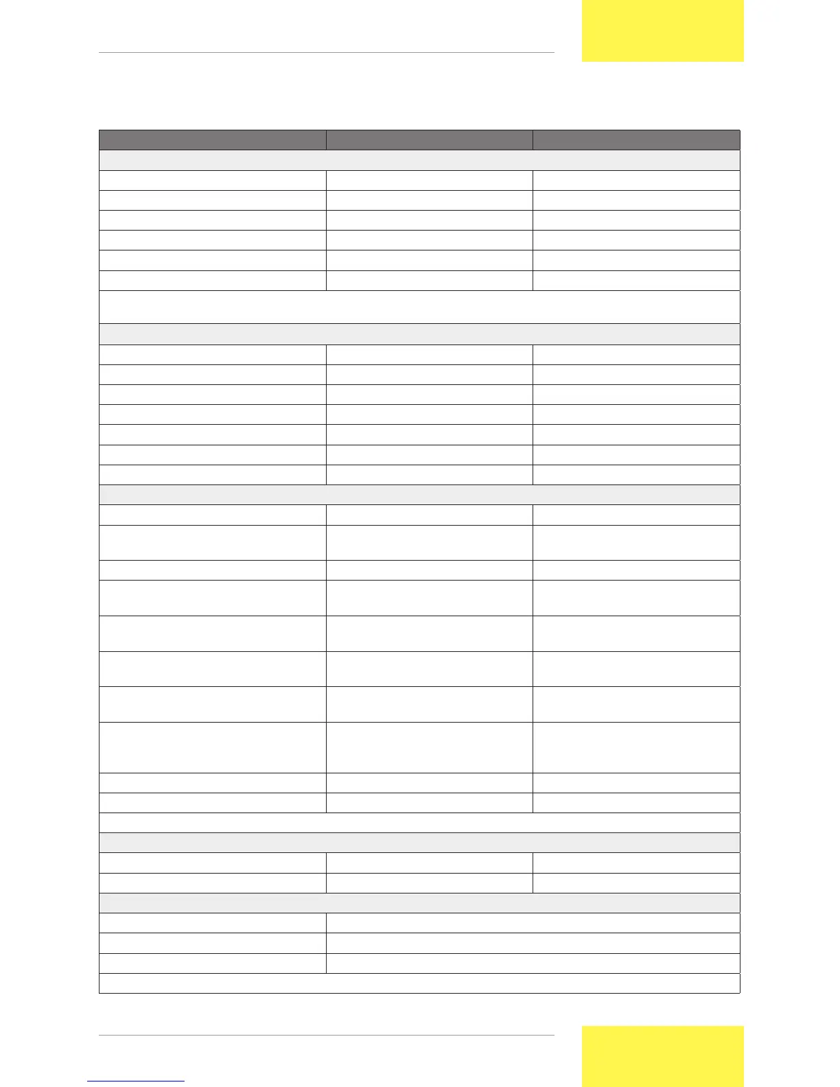
6 Technical specifications
StecaGrid 300 StecaGrid 500
Input
Input voltage range 45 – 135 V DC 75 – 230 V DC
MPPT range 45 – 100 V DC 75 – 170 V DC
Maximum recommended PV power 375 Wp 625 Wp
Maximum input rating 320 W
(1)
530 W
(1)
Maximum input current 5 A
(1)
5 A
(1)
DC connectors Multi-Contact MC 3, MC 4 Multi-Contact MC 3, MC 4
(1)
Greater available input power and/or higher available current are not utilised as the inverter contains a protection against over-
load.
Output
Nominal output rating 300 W 500 W
Nominal output voltage / frequency 230 V / 50 Hz 230 V / 50 Hz
Maximum efficiency 94.8 % 95.8 %
European efficiency 93.4 % 94.5 %
Power factor > 0.95 > 0.95
Harmonic distortion < 6 % (at maximum power) < 5 % (at maximum power)
AC connectors Wieland Electric GST 18i3V Wieland Electric GST 18i3V
General
Galvanic separation none none
Internal power supply supplied by solar panel
(no Stand-by power)
supplied by solar panel
(no Stand-by power)
Start-up/switching off Automatic start / stop Automatic start / stop
Start current Starts up at > 2 W, 45 V
input voltage
Starts up at > 2 W, 45 V
input voltage
AC monitor Voltage (230 V +/-10%)
(2)
Frequency (50 Hz +/-2 Hz)
(2)
Voltage (230 V +/-10%)
(2)
Frequency (50 Hz +/-2 Hz)
(2)
Grid monitoring in the
StecaGrid 300 UK or 500 UK versions
Voltage (230 V +/-10 %)
Frequency (50 Hz +0.5 Hz/-3 Hz)
Voltage (230 V +/-10 %)
Frequency (50 Hz +0.5 Hz/-3 Hz)
Grid monitoring in the
StecaGrid 300 ES or 500 ES versions
Voltage (230 V +10 %/-15 %)
Frequency (50 Hz +/-1 Hz)
Voltage (230 V +10 %/-15 %)
Frequency (50 Hz +/-1 Hz)
Anti-islanding protection Voltage and frequency window
monitoring; ENS optional with
StecaGrid ENS26
Voltage and frequency window
monitoring; ENS optional with
StecaGrid ENS26
Dimensions (X x Y x Z) 176 x 243 x 71 mm 176 x 243 x 71 mm
Weight 1.4 kg 1.4 kg
(2)
Other limit settings are also available ex works
Environmental conditions
Temperature -20 °C to 45 °C -20 °C to 45 °C
Installation Indoors (protection class IP 20) Indoors (protection class IP 20)
Installation and connection
Installation of a single inverter Three fixing screws
Installation of two and more inverters DIN rail
Interconnection AC side AC connector (Wieland Electric GST 18i3V 1P1)
(3)
(3)
The coupler plug is supplied with the inverter.