3
35. CD2–ManualEjecthole
36. 45rpmSpindleAdaptor
37. TurntableSpeedSelector
38. AutoStopSwitch(ON/OFF)
39. PitchControl
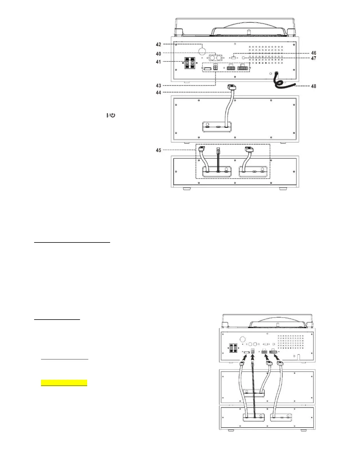
40. Line‐OutSocket(RCA/L+R)
41. SPEAKERSockets(L+R)
42. FM/DABAntennaSocket
43. SOCKET
44. CassettePower/SignalCable
45.
CDPowerSupplyCable/CDSignalCable
46. ErPON/OFFswitch
47. SUBWOOFER‐outsocket
48. PowerCord
49. BTT(BluetoothTransmit)LEDIndicator
50. PowerOn/OffButton
51. X‐BassButton
52. StrobeLens
CAUTION:
USAGE OF CONTROLSOR ADJUSTMENTS OR PERFORMANCE OF PROCEDURESOTHER THANTHOSESPECIFIEDHEREIN MAYRESULT IN HAZARDOUS RADIATION
EXPOSURE.THEREFORE,THISUNITSHOULDNOTBEADJUSTEDORREPAIREDBYANYONEEXCEPTQUALIFIEDSERVICEPERSONNEL.
PREPARATIONSFORUSE
INSTALLATION
Unpackallpartsandremoveanyprotectivepackingmaterials.
Pleasekeepallpackaginguntilyouhavefullycheckedallpartsoftheunitareworkingcorrectlyandforfutureuseincasethe
unitneedsservicing.
EnsuretheRemoteControlandanyotheraccessorieshavebeentakenout
ofthepackagingbeforestoringtheboxaway.
Thisunitisoperatedby230V~50HzACmainsonly.
Do not connect the unit to the mains before checking the mains voltage is correct for the unit and before all other
connectionshavebeenmade.
Whenpositioningthe
unit,nevercoveranyventsandmakesurethatthereisaspaceofseveralcentimetersaroundtheunit
forventilation.
CONNECTIONS
This main music system consists of three parts‐the top record player unit with
maincontrolsandamplifier,themiddledoubleCassettePlayer/Recorder,andthe
bottom CD Player/Burner unit.Before using the system,these need to be
connectedfirst,andsowillthesepar atespeakers.
1. Assemblethesystem:
PlacetheCDPlayer/Burnerunitatthebottom,then
placetheCassettepartinthemiddleandfinallythemainunit(recordplayer)
ontop.
2. Connectthe4cables:Connectthecable(44)fromthemiddlepartandthe
cable(45)fromthebottompart,intothemainunit ’s sockets(43)inthe
directionasshowninthediagramontherighthandside.