EF315_r5.1(v12.22) – 03/2023 page 8
In case of active errors or alarms, the related messages are displayed on the fourth line, in place of the
temperature.
If the temperature display is programmed on the third row, it is shown alternating with the injected
volumes and working thresholds.
From this screen, pressing the arrow keys, specific
displays will be visualized for each measurement,
for example:
The top row shows the final measurement (with
offset and gain corrections), then will follow - within
brackets - the value measured by the instrument
before the corrections, and finally the offset and gain factors.
In this specific case, the electrode has an offset of -0.17pH and a gain value of 1.038. Further details
about the importance of these correction factors can be find in the following sections.
Press again the arrow keys to display the details of the remaining two measurements.
ELECTRICAL CONNECTIONS
Normally the device is supplied prewired and assembled on a panel. However, this section provides info
about the electrical connections to be performed by technical personnel only.
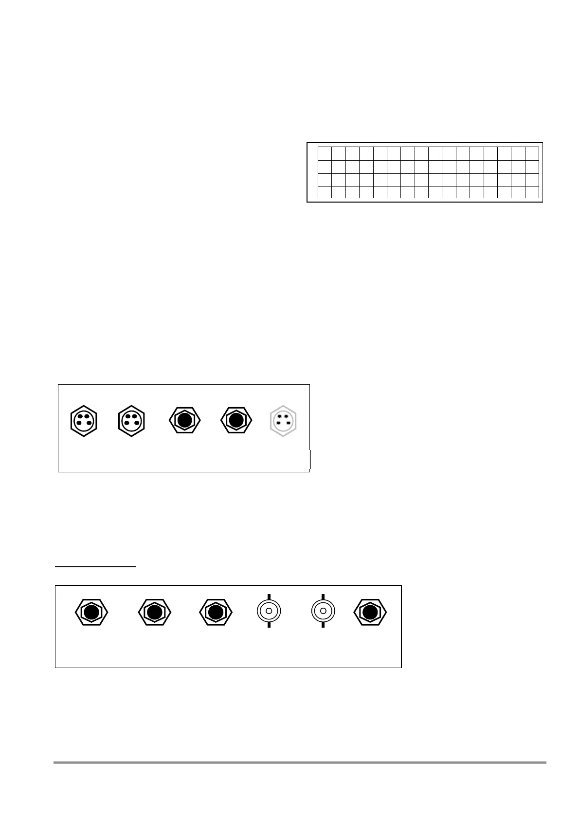
View of the right side:
• LEV.1: connector for level sensor of tank 1 (acid)
• LEV.2: connector for level sensor of tank 2 (chlorine)
• FLOW: input for NPN micro-magnetic flow sensor
• EXT.CONS.: OFF contact from contactor
• RS232: (optional) RS232 port wired on M8 connector
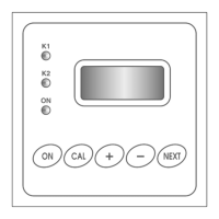
Version pH/RX
Front view:
• POWER: power cable (prewired)
• OUT1: driving output for pump 1 (pH control)
• OUT2: driving output for pump 2 (chlorine control)
• pH: BNC connector for pH electrode
• Redox: BNC connector for redox electrode
• PT100: input for Pt100 sensor
7
. 2
3
p
H
POWER OUT1 OUT2 pH Redox PT100
(pH) (Chlorine)
LEV.1 LEV.2 FLOW EXT.CONS. RS232