12
Installation instructions
Dear Customer,
Congratulations on purchas-
ing this STEINEL Infrared
Sensor and thank you for
the confidence you have
shown in us. You have
chosen a high-quality
product that has been
manufactured, tested and
packed with the greatest
care.
Please familiarise yourself
with these instructions
before attempting to install
the sensor since prolonged
reliable and trouble-free
operation will only be
ensured if it is installed
properly.
We hope your new Infrared
Sensor will give you lasting
satisfaction.
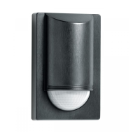
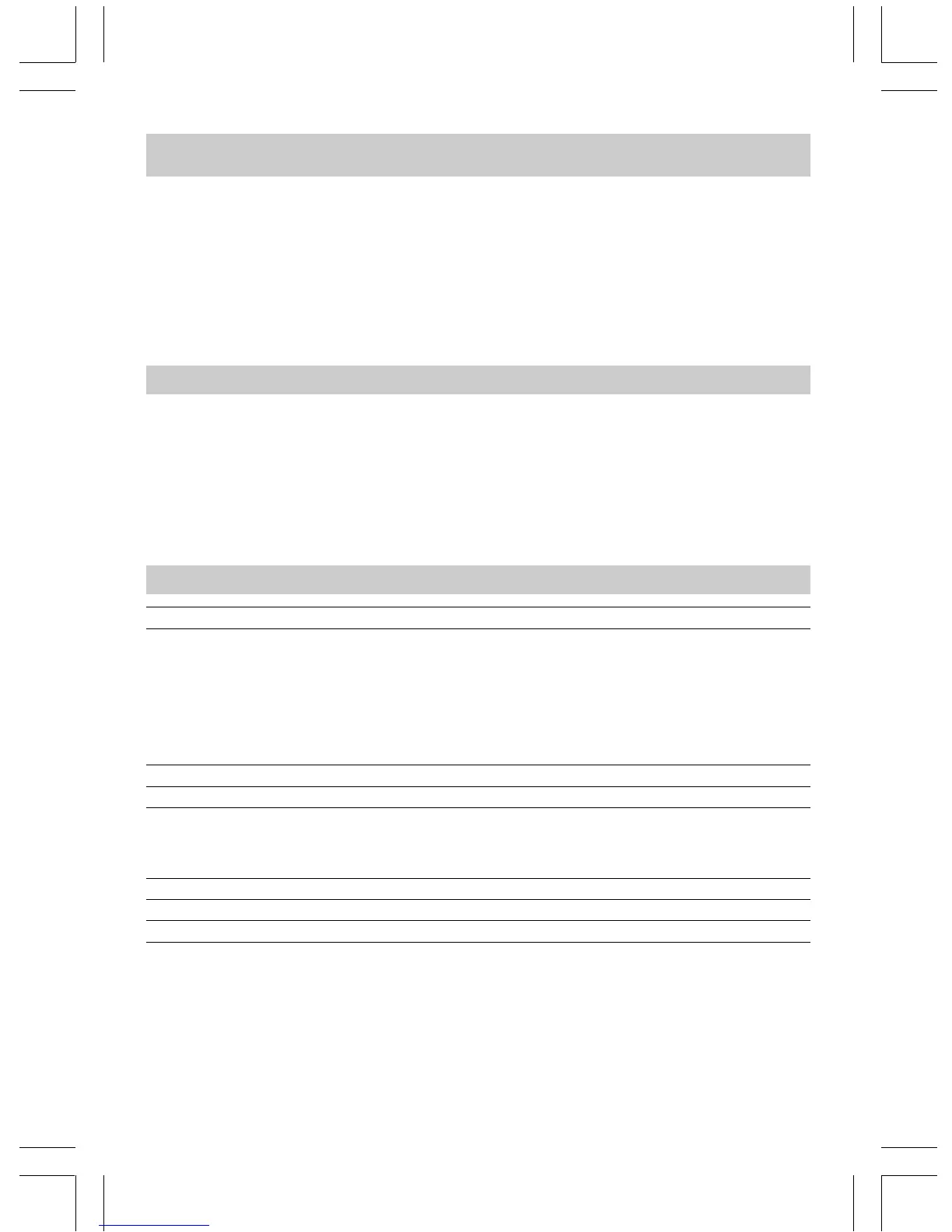
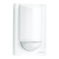
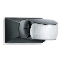
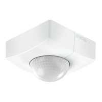
System components
Security screw
Front cover
Lens (can be removed
and turned for selecting
the max. basic reach
settings of 5 m or 12 m)
Light threshold setting
control 2–2000 lux
Time setting control
10 sec.–15 min.
Clip (housing can be
flipped up for assembly
and connection to mains
power supply)
Dimensions: (H x W x D) 120 x76 x56 mm
Output: 1000 watts max. (resistive load, e.g. filament bulb)
500 watts max. (uncorrected, inductive,
cos φ = 0.5, e.g. fluorescent tubes)
900 watts max. (series compensation)
500 watts max. (shunt compensation,
at C = 45.6 µF)
600 watts max. (electronic ballasts, capacitive
e.g. low-energy lamps, 8 each max.)
Connection: 230 - 240 V, 50 Hz
Detection angle 180° horizontal, 90° vertical
Sensor reach: basic setting 1: 5 m max.
basic setting 2: 12 m max. (factory setting)
+ precision adjustment from 1 - 12 m by means
of clip-on shrouds
Time setting: 10 sec. – 15 min. (factory setting: 10 sec.)
Light threshold: 2–2000 lux (factory setting: 2000 lux)
Enclosure: IP 54
Technical specifications