DM556T Digital Stepper Drive User Manual
of +24 - +48 VDC, leaving room for power line voltage fluctuation and back-EMF.
Higher supply voltage can increase motor torque at higher speeds, thus helpful for avoiding losing steps. However,
higher voltage may cause bigger motor vibration at lower speed, and it may also cause over-voltage protection or
even drive damage. Therefore, it is suggested to choose only sufficiently high supply voltage for intended applications.
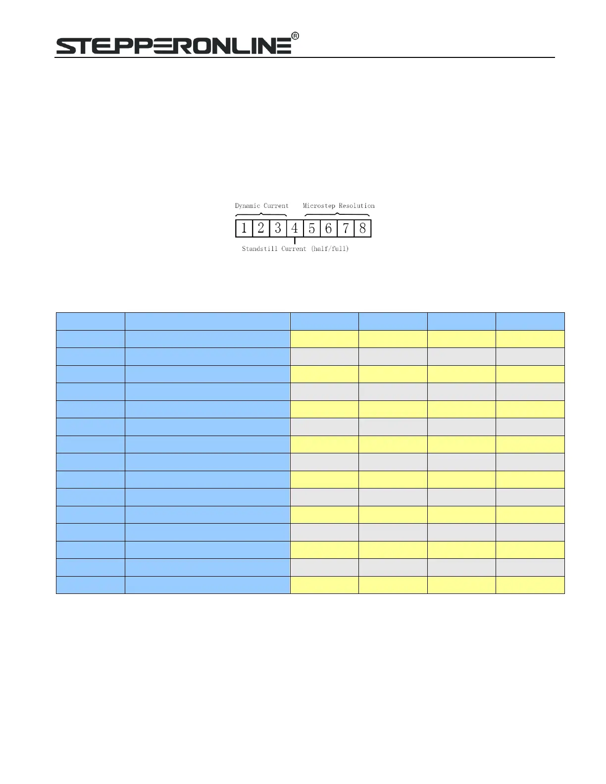
7. DIP Switch Configurations
This drive uses an 8-bit DIP switch to set microstep resolution, and motor operating current, as shown below:
7.1 Microstep Resolution Configurations
Microstep resolution is set by SW5, 6, 7, 8 of the DIP switches as shown in the following table:
Steps/rev.(for 1.8°motor)
7.2 Current Configurations
For a given motor, higher drive current will make the motor to output more torque, but at the same time causes more
heating in the motor and drive. Therefore, output current is generally set to be such that the motor will not overheat
for long time operation. Since parallel and serial connections of motor coils will significantly change resulting
inductance and resistance, it is therefore important to set drive output current depending on motor phase current,
motor leads and connection methods. Phase current rating supplied by motor manufacturer is important in selecting
drive current, however the selection also depends on leads and connections.
The first three bits (SW1, 2, 3) of the DIP switch are used to set the dynamic current. Select a setting closest to your

 Loading...


