The DM556T is a 2-phase digital stepper drive designed for controlling stepper motors. It features a simple design and easy setup, making it suitable for various applications requiring step and direction control. The drive utilizes advanced stepper control technology to ensure smooth operation, optimal torque, and reduced motor heating and noise. It is compatible with 2-phase (1.8°) or 4-phase (0.9°) NEMA 23, 24, and 34 hybrid stepper motors.
Function Description
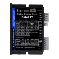
The DM556T operates with an input voltage range of 20-50VDC and can deliver an output current of up to 5.6A. All micro-step resolutions and output current settings are configured via DIP switches, simplifying the setup process. The drive supports both differential and single-ended inputs, including open-collector and PNP output, through its optically isolated logic inputs on connector P1. These isolated inputs help minimize electrical noise interference with control signals.
The drive incorporates several key functionalities:
- Anti-Resonance: This feature optimizes torque, ensures extra smooth motion, and reduces motor heating and noise.
- Motor Auto-Identification and Parameter Auto-Configuration: Upon power-on, the DM556T automatically configures itself with optimal settings to match the connected stepper motor, ensuring peak performance without manual intervention.
- Step & Direction Control: The drive uses PUL/DIR control signals for precise motor movement.
- Multi-Stepping: This function enables smoother motor movement.
- Automatic Idle-Current Reduction: This feature helps reduce motor heating when the motor is at a standstill.
Usage Features
The DM556T offers a range of features designed to enhance usability and performance:
- DIP Switch Configuration: Micro-step resolution and output current settings are easily adjusted using an 8-bit DIP switch. There are 16 selectable micro-step resolutions ranging from 400 to 25,600 steps/rev for a 1.8° motor, and 8 selectable output current settings from 1.8A to 5.6A.
- Soft-Start: The drive initiates operation with a soft-start, preventing any sudden "jump" when powered on.
- High Pulse Input Frequency: It supports a pulse input frequency of up to 200 KHz.
- TTL Compatible and Optically Isolated Inputs: The control signals are TTL compatible and optically isolated, improving noise immunity.
- Motor Connection Flexibility: The DM556T can drive 4-lead, 6-lead, or 8-lead bipolar hybrid stepper motors. For 6-lead motors, both half-coil (higher speed) and full-coil (higher torque) configurations are supported. For 8-lead motors, series (higher torque at lower speed) and parallel (higher torque at higher speed) connections are available, offering flexibility for various application requirements.
- Power Supply Selection: Both regulated and unregulated power supplies can be used. Unregulated power supplies are generally preferred due to their ability to handle current surges. Multiple DM556T drives can share a single power supply if it has sufficient capacity, provided each drive is connected separately to avoid cross-interference. The recommended supply voltage range is +24V to +48VDC, allowing for fluctuations and back-EMF.
Maintenance Features
The DM556T incorporates several features to ensure reliability and ease of maintenance:
- Protection Functions: Built-in protections include over-current and over-voltage.
- Over-current protection: Activated when the peak current exceeds its limit.
- Over-voltage protection: Activated when the drive's working voltage exceeds 60VDC.
When these protections are active, the motor shaft becomes free, and a red LED blinks to indicate the fault. The drive can be reset by repowering it after resolving the underlying issue.
- LED Light Indication: The drive features two LED lights:
- A GREEN LED indicates power and is generally always on.
- A RED LED serves as a protection indicator, flashing 1-2 times in a 3-second period when a protection function is enabled. Different flash patterns correspond to different protection types.
- Heat Dissipation Recommendations: To ensure reliable operation, the DM556T's working temperature should remain below 60°C (140°F).
- It is recommended to use the automatic idle-current mode (SW4 pin set to "OFF") to reduce motor heating.
- Mounting the drive vertically is suggested to maximize the heat sink area.
- Forced cooling methods should be employed if necessary to maintain optimal temperature.
- Wiring Notes: To improve anti-interference performance, using twisted pair shielded cables for control signals is recommended. Control signal wires and motor wires should be kept separate (at least 10 cm apart) to prevent interference. It is crucial not to plug or unplug the terminal blocks (P1 & P2) while the DM556T is powered on, as this can cause high back-EMF voltage surges and potentially damage the drive.
- Troubleshooting Guide: The manual provides a comprehensive troubleshooting section to help identify and resolve common issues, such as the motor not rotating, rotating in the wrong direction, erratic motion, stalling during acceleration, or excessive heating. It emphasizes documenting each step of the troubleshooting process to assist technical support if needed.
- Warranty: The product comes with a twelve-month warranty against defects in materials and workmanship, with options for repair or replacement. Exclusions apply for damage due to improper handling, unauthorized modification, or operation outside electrical or environmental specifications.