DM556T Digital Stepper Drive User Manual
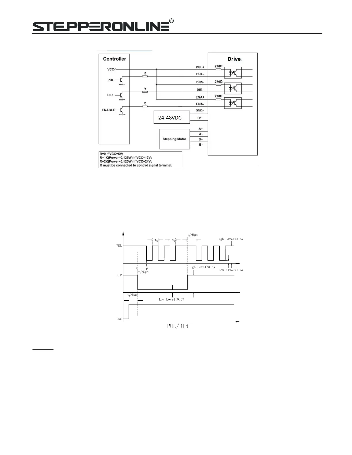
generator). A typical connection is shown as figure 9.
Figure 9: Typical connection
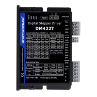
10. Sequence Chart of Control Signals
In order to avoid some fault operations and deviations, PUL, DIR and ENA should abide by some rules, shown as
following diagram:
Figure 10: Sequence chart of control signals
Remark:
a) t1: ENA must be ahead of DIR by at least 5s. Usually, ENA+ and ENA- are NC (not connected). See
“Connector P1 Configurations” for more information.
b) t2: DIR must be ahead of PUL effective edge by 5s to ensure correct direction;
c) t3: Pulse width not less than 2.5s;
d) t4: Low level width not less than 2.5s.