Do you have a question about the StepperOnline DM860T and is the answer not in the manual?
Overview of the DM860T digital stepper drive and its advanced control technology.
Highlights key capabilities like anti-resonance, auto-identification, multi-stepping, and protection functions.
Describes suitable uses in machines like CNC, engraving, and pick-place devices for high precision.
Details voltage, current, frequency, and pulse width parameters for the drive.
Covers ambient temperature, humidity, vibration, and cooling requirements for optimal operation.
Presents physical dimensions and mounting recommendations for the drive unit.
Provides guidance on managing drive and motor temperature for reliability and performance.
Details the pin functions for control signal connections (DIR, PUL, ENA).
Explains jumper settings for pulse edge, direction, and control modes (PUL/DIR, CW/CCW).
Details the pin functions for power supply and motor phase connections (A+, A-, B+, B-, AC).
Guides on wiring 4-lead stepper motors, including current setting adjustments.
Describes wiring configurations for 6-lead motors for high speed or high torque.
Explains using half the motor windings for lower inductance and smoother high-speed operation.
Details using full motor windings for higher torque at lower speeds, with current derating.
Covers flexible wiring options for 8-lead motors in series or parallel configurations.
Explains series wiring for higher torque at lower speeds, noting inductance impact.
Describes parallel wiring for stable low-speed operation and higher torque at high speeds.
Compares AC and DC power options, recommending AC for higher torque and discussing supply types.
Provides recommendations for connecting multiple drives to a single power supply safely.
Guides on choosing appropriate supply voltage for optimal performance and avoiding damage.
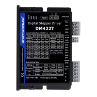
Details how to use DIP switches (SW5-SW8) to set microstep resolution for smoother motion.
Explains how motor current affects torque and heating, and how to select it.
Covers setting the peak output current using DIP switches (SW1-SW3) based on motor requirements.
Explains using DIP switch SW4 to set standstill current to half or full dynamic current.
Describes the drive's feature to automatically identify motor parameters for optimal torque.
Clarifies signal timing parameters like pulse width, delay, and level width for PUL, DIR, and ENA.
A troubleshooting guide linking common motor and drive issues to their likely causes and solutions.
| Pulse Input Frequency | 200 kHz |
|---|---|
| Cooling Method | Natural Cooling |
| Operating Temperature | 0°C to 50°C |
| Storage Temperature | -20°C to 70°C |
| Protection Features | Over-voltage, Over-current |
| Humidity | 90%RH |
| Logic Input Current | >= 10 mA |